The Ultimate IH Fourbanger

The log style manifold would need to be built such that the bolts that attach it to the head were either below or above the log. Either that or the log is set out wide so you could install and tighten the bolts between the log and the head. I thought space would cause issues.

That factored into my decision to test fit the wedge/spacer.

One caveat on having the turbo and other masses hi high and above the engines center of mass is that it is subject to a lot more transverse displacement vibration than down low and close to the crank center line. That being said, I could be wrong (not surprising to me) by the way, and most of the vibration displacement is vertical.

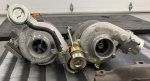
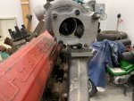
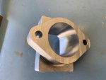
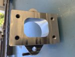
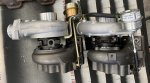
You brought up physical turbo size so here is a photo or two of both of my modern turbochargers. The one with the silver wastegate diaphragm is the gt2252 the other is the gt2554R.

The gt22 actually flows better through the turbine ,but nets a lower air flow than the gt25. The gt22 is oil only and journal bearing center section while the GT25 is oil lubricated and water cooled, and is a ball bearing.
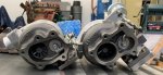
IMG_4120crop.jpg

IMG_4121crop.jpg

IMG_4122crop.jpg
 
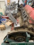
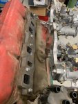
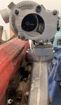
Looking at the end-view pic of the wedge/manifold. Imagine just the wedge bolted up, with a heavy wall log, say, 2" or 2 1/4" OD, lying against it. That log would be in about the same place as the main body volume of the up-turned iron manifold. So the log would be spaced out the distance of the wedge. From what I'm seeing, that would still allow clearance to remove the plugs (a super pain nonetheless); four very short, heavy-wall schedule 40 sections would replace the wedge, bridging the gap between your exhaust header flange and the log. Then the turbo flange is welded to a short section welded onto the log. This flange mounting surface would be located in space at about the height of your manifold + your anticipated spacer mounting surface. As far as flow through the log is concerned, would it be worse than as through the stock manifold? Would it even matter? In the end the question is making a weldment as strong as those iron pieces to support the turbo without shaking and cracking.

Edit: Oops - haven't forgotten the most important thing. The center axis of this log will be just high enough above the centerline of the exhaust manifold mounting bolt holes so the bolts will clear! I think that can be done.
 
Some progress on this project.
1) Rotated the center bearing unit so the drain is down.
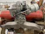
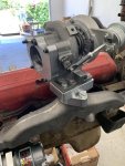
2) With the stock designed 2 bolt manifold I played with optimized turbocharger mounting and orientation.
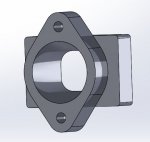
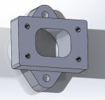
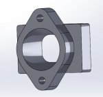
3) Created a solid model for a one piece Turbo inlet transition. I'll use this to create the tool paths and wire EDM geometry/program. The one piece transition will sit the turbo about 3/4" higher than the pictures here.
4) Bought the turbine outlet plate, and the azzhats missed on a hole location. So I fixed that. You can see it in the photos

Oh yeah, to Marks question regarding boost, the waste gate is set for 10psi. But I don't see that as a limit.

A few snips of the model. and how I will orient the turbo. About 15 deg. clocked CCW leaves the ports in better locations for plumbing.

gt2252 inlet transition.JPG

gt2252 inlet transition2.JPG

IMG_4179.jpg

IMG_4180.jpg

IMG_4182.jpg
 
Last edited:
Kind of a wait and see. I envision an air cleaner housing on the passenger side front inner fender. Still looking for a suitable one.
Turbo outlet, down and in between the middle two intake runners, forward into the intercooler, and back, and up into the intake plenum.
 
I decided to have my turbo mount adapter made out side. Just don't have time to do it in house. It's in line at a friends CNC shop. Should see it in a week.
 

Attachments

  • gt2252 inlet transition.JPG
    gt2252 inlet transition.JPG
    25.6 KB · Views: 595
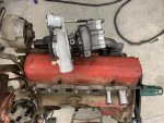
I have then adapter in hand, fresh off the VMC. Works as expected. While this is a small turbocharger the adapter will allow multiple larger options down the road. The 152 IH with it's flow characteristics and operating range, fit perfectly with the flow maps delivered by my current choice.

I fabricated a fixture system that will allow me to locate and lock the carburetors for manifold runner fab and creation. So far the envelope dictated by the scout 80 firewall is very doable.

IMG_4215.jpg

IMG_4218.jpg

IMG_4219.jpg

IMG_4220.jpg

IMG_4222.jpg
 
Very nice!

If it wouldn't be toooo much trouble, a view from the back end, looking forward, centered about the top of the valve cover, to see how high that turbo sits, would be nice.
 
Last edited:
It does, thanks. And when you have a little more time for a couple of critical measurements, exactly what is the distance from the highest point of the valve cover to the top of that turbo? Thinking about under hood clearances. You are looking at worst case here, as an early is rotated 15 degrees inward and your turbo sits higher. An early, IIRC, will have greater clearance than a Scout II. Which brings me to the second measurement. Can you rotate your engine 15 degrees outward - as if it were mounted like a V8 - and grab that same metric? That would give me an idea of how it would fit under a Scout II hood. With the set up I had with the OEM turbo, I had about 3/4", and it was a bit too close for my comfort. To whatever distance you get, I would add about another 1/2", as a 196 is taller than a 152. I am hoping that your arrangement, with a smaller turbo, will make a significant difference in under hood clearance.
 
I can give you the measurements as it stands now for sure, rotating it to 45deg is an other thing.. It took quite a bit of finagling to get the engine to sit on the stand like it is in a scout 80. If one of the stand index pin holes is about where it needs to be I'll try.
I have a bunch of irons in the fire at the moment, so give me a few days, maybe Saturday for the measurements.
 
As it stands now is fine. Perhaps the other when convenient. Progress comes slowly with projects such as these...
 
Last edited:
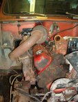
This is the best pic I have that illustrates the differences between your installing your 152 into an early 80 series vs. a 196 in a Scout II where the 1/2 V8 rotates back to the normal mounting scheme. Clearance with the TRW turbo was pretty close to the underside of my hood (mostly the reinforcing web). It will be interesting to see how high your turbo sits, and how it would sit rotated back to its normal location. Although the 196 block is an inch or so higher, any turbo won't sit that much higher (trigonometry and all that, you know). Anyway, we'll eventually have an answer to this. Looking at the surfaces things mount to, we have the V8 as a 90 degree vee, so the centerline of the piston bores is 45 degrees from vertical. The exhaust ports themselves appear, as best I can determine, 30 degrees from the vertical. That's why, in this pic, the interface between the wedge and exhaust manifold is vertical. And the plane of the manifold outlet is not horizontal, but tipped (rotated) 15 degrees from the horizontal. Thus the wedge provides a 15 degree correction. If I go this route - machining a wedge - I would still need to make an manifold adaptor-to-turbo spacer with a 15 degree taper to make the turbo base plate horizontal. Maybe this is not essential. Please review my assessment of these angles to see that I have not suffered a brain fart and can't smell it. :icon_rotate:
 

Attachments

  • Picture 050.jpg
    Picture 050.jpg
    62.9 KB · Views: 552
Got your measurements today, as you know. I just now measured that distance from top of valve cover to the top of your turbo. It is several inches shorter than the height of the TRW turbo in my pic (above). So under hood distance is significantly improved. Yay!
 
Just emailed you a sketch to confirm configuration and some measurements.

Regarding the height of your turbo, the height I measured (your 5 7/8") from the peak of my valve cover is still about 2" lower than the top of my air cleaner. That is excellent clearance.
 
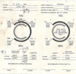
How does this compare to the normal regrind that Jeff sells? That's what I have. It ups the exhaust lift a little bit.

And I looked over all those pics you sent. What a fascinating piece of casting TRW produced for IH. I believe I now have enough pics and dimensions so that one could make a good stab at machining a functional wedge. When time permits, of course.

Question regarding your turbo mounting: You have the base of the turbine housing sitting horizontal, and the compressor housing is "overshot". The waste gate has a specific geometry, it seems. Your exhaust exits rearward. For me, I was envisioning roughly the same kind of mounting orientation as I had before. Your turbo would sit about at the same level, but can it be reversed, so that the compressor is undershot (even if I had to rotate it pointing more upward), and the exhaust outlet would face forward? That waste gate looks like it would be problematic.
 
Last edited:
BBC Scat 6.385 C to C rods, have them
Custom forged pistons to my drawings, likely Wiesco. Used them many times for various custom applications.
I have the crank done already, narrowed journal, welded and ground to 3.75 stroke
 
BBC Scat 6.385 C to C rods, have them
Custom forged pistons to my drawings, likely Wiesco. Used them many times for various custom applications.
I have the crank done already, narrowed journal, welded and ground to 3.75 stroke
any chance you want to sell them? Picking up a 152 tomorrow that I would like to stroke. Also where you planning on using the 152 head or something else?
 
Back
Top