Switchable Dual Batteries

Ok I got the 10ga blue hooked up right now, but only one item still does not seem quite right. With the engine running,, when I turn the bat selector switch to "off" the engine keeps running. Which tells me I am running off the alternator alone, that does not seem quite right, but I May never use the "off" position. Maybe thats normal, like disconnecting the battery with engine running.

Other than that the system is pretty nice. Now if I can ever get my borther in law to finish my winch bumper:icon_xd:. I guess getting married is more important than working on my bumper:crazy:

thanks for all the help, patrs list, install info and touble shooting.

Ron
 
I believe the 95 amp version has been discontinued though they are still found everywhere on the shelves!

The 120a version is just fine, far more ampacity than you will ever need.

also...regarding the battery selector switch, the one I used does not have the "field disconnect" feature. Therefore you never move the switch while the engine is running. If ya do, you will toast the diode block in the alternator.

The various battery selector switches that do have the field disconnect feature May be "switched" with the engine running, though you never turn the selector off with the engine running, bet you can understand why!

The install kits that surepower packages include 6 gauge wire, major overkill that is great! The oem shit is a 10 gauge circuit, so I rewire the oem charge lead with 6 gauge also. Crimping 6 gauge insulated or copper lugs can be a bitch if ya don't have a texas aggie toenail clipper.

Duh!! I should comprehend what I read.:incazzato:
ron
 
Man I really scruud up and simply did not see your posts ron!

Then while responding this morning, an accident downriver wiped out all electricity and cell/landline communications in the entire valley, we just got dsl back a few minutes ago, cell service is still out. I did manage to save this response this morning after I-net access died.

But Matt covered everything in well-spoken english and dam he did a guud job! And so did you!

Yawl need to know...about five years ago when Matt accosted me at the Binder Bee for some "help", he didn't know which way to turn the key to start a Scout II! All he knew was that once a week he traded dollars for gasoline somewhere, and since he's in orygone he didn't even have to git out of the cab to pump it!

Matt helps out all kindsa folks 24/7 with healing in their lives, but he dam shore couldn't heal any thing that required a hand tool.

Fast forward five years, dude is dam near a full-fledged journeyman meekanik! And his wife and kids encourage his continuing education so in the future he can add to his repertoire now he's taken up marine mekanikin' too, on mercury outboard carburetors no less! He'll need that when noah's flood comes back around after them polar ice caps finish meltin'.

Back to the subject...there are several ways of incorporating the "switchable" dual battery setup, ya just gotta have a basic knowledge of the charging system and the design limitations of the IH-produced stuff in particular, mainly the bulkhead connector issue, the bogus "ground" system, and the use of the ammeter as the primary current feed for all electron distribution.

Use of the marine-type battery selector switch is somewhat unique in our world, most folks want some kinda dash control or "automatic" function for that, but not me, I can still open the hood and handle a good old hd mechanical switch without the gummint doin' it for me! And $40 for that switch instead of $350 for the "automatic" crap sure helps in the budget department!

Another piece of advice...swap back and forth between the two batteries monthly to exercise the auxiliary through a few discharge/charge cycles (engine starting). "wet" type batteries (whether flooded cell or agm) need exercise and that also tells ya everything is working properly. If I had done that I would not have allowed my optima yellow top to go bad to the tune of $185 after only three years.
 
No problemo Mike, Matt was a big help! He cleared the fog when I was wiring the iso, I was going by the surepower wiring instructions and did not combine the oem connections (duh). But we gottr done!
I will try to post some pics in a few days, I am going out of town on work, looks pretty much like Matt's except for a custom battery tray. I tried one like Matt's but did not like the way it had to be held an inch away from the vertical wall of the inner fender because of the hold down. So I built one that the hold down is length wise to the battery and the tray bolts to both the horizontal and the vertical wall of the inner fender. It made the battery more solid in the tray and the battery does not stick any further into the engine compartment than it has to.
I aslo used ring terminals on everything with marine grade battery post connectors (wing nuts). The terminals are rated for the 2ga wire so they should work, but May require a little extra maintenance to keep them clean, we will see.

Good tip on battery exercise though, I also used a yellow top for my 2nd battery I have plans to install one for the crank battery also.

Off topic; you mentioned Matt's wife being supportive, man my wife was actually turning wrenches with me. She handled the relocation of the windshield washer res (did a good job to) and helped me put the radiator back in the 75. I even caught her on ebay looking at scouts:cornut: who knows we might be looking at a his/hers Scout family in the future. Not braggin but it was a first in my shop.

Thanks
ron
 
Last edited:
These lifepartners just gotta warm up to this oldiron stuff ron! And it helps if they don't experience too many breakdowns on the road! We look at that as an adventure, wimminfolk look at it as a disaster and crisis!

Running dual yellow tops is an excellent idear, wish I'd done that looking back when I invested in the optimas. The deep cycle yellows serve just fine as crank batteries, especially on the IH stuff since cranking requirements are so mild! My mistake (I thought I was smarter than johnson controls!) was in mixing the chemistries!

Johnson controls clearly advises to not mix batteries of different chemistry in multiple battery systems. And the isolator folks all advise using multiple batteries that are new and "matched" (meaning they carry the same "lot" number code).

The alternator can only produce one "charge rate" and that is based upon the most needy battery in the system. A single alternator can't charge at two different rates, and the isolator only prevents a low voltage battery from discharging a "charged" battery in an attempt to equalize charge level chemically.

In my case, I made the sitch even worse! I had a red top and a yellow top combined under the hood, the proper "terminal voltage" between those two chemistries is significantly different as to what constitutes a fully "charged" battery.

Then...when the trailer is connected, that added into the entire charging system, two additional batteries, one was a conventional flooded cell deep cycle, the other a red top. Total wrong combo! So charging four batteries off a single alternator through an isolator is really dumb! Yes, the alternator is perfectly capable of doing this (and did so for nearly three years), but only the red top crank battery was ever fully charged at any one time when driving down the road.

When the trailer is plugged into shore power, the on-board charger charges the house batteries at the proper "rate", but since there is no isolator on the trailer from that end, then the mismatched batteries also would not allow the red top to fully charge as the chemistries are significantly different!

In that case, the only thing I did right when the trailer was plugged into shore power, was to disconnect the trailer harness so the trailer charge could not attempt to charge the tow rig batteries. To run the four battery setup, I should use two isolators, one mounted in the trailer system.

When I hit the lottery, I will have four matched optima blue top sparkers! Two under the hood, and two in the trailer...that is the ultimate "dry camp" weapon! That's about $800 in batteries right now locally! That gives me three batteries for the trailer, and keeps the crank battery out of the loop for discharge for long-term dry-camp.
 
yawl need to know...about five years ago when Matt accosted me at the Binder Bee for some "help", he didn't know which way to turn the key to start a Scout II!
Wait a sec... scouts actually start??? :)

thanks for the props kimosabe - it's all about quality instruction from binder u! Your tuition rates stinkin' rule too, btw. :ihih: now that my daughter helped me rebuild the mercury carb (that little motor screams now!) it's an intractable, full-on family thang.

Best deal on the ladyfolk end of things is to show them how useful all this old garbage iron can be! About 6 months after installing my dual batteries (which my dear wife thought was a total waste of time, but she encouraged me anyway 'cause she knows what "wrench therapy" means) the oem battery in her honda accord croaks at a gas station in a driving rainstorm. She's stranded and in danger of missing a dr. Appointment, so she calls me in a mild panic. I rush over to the station, pull the dead lead out of the honda, rip my optima red top crank battery out of the Scout & drop it in the honda, then relocate my aux battery and re-fire the Scout sans problema. The honda fires right up, she looks at me like I'm a stinkin' genius, makes her dr. Appointment on time, and promises me she'll never complain about my dual battery setup again! :cornut:

thanks for the info on working out the aux battery once in a while. I never do that but I should, and I know enough about batteries that I shoulda' figured that out on my own. Oh well, maybe this old napa aux battery will die soon and I can put another red top in there. :icon_wink:
 
Well I thought I would post my dual battery install (copied from Matt) looks the same as Matt's but I wanted to show the battery tray I made. It is as solid as a rock.
dscf1613.jpg

dscf1614.jpg


Ron
 
I noticed a lot of guys use isolators, but is it necessary to get a diode style and a selonoid style like in the op's photos or can I get away with just the diode style? Also if anybody can recommend a cheap place to get 2 gauge wiring I would really appreciate it!

Update: nevermind! I see what the solonoid is for now! I found a great diagram that dumbs this down enough even for me. The bottom of page 2.


http://www.surepower.com/pdf/180012q.pdf
 
Last edited:
Using an isolator is far more modern and technically advanced than using the relays as we did back in the 50's and 60's.

The isolator blocks can take unlimited lifetime cycles of use, the relays have a calculated duty cycle just like a battery. And they are an electromechanical component that is subject to failure at any time.

I source 2 gauge battery cable at any local auto supply. Both in bulk on spools (sold by the foot) or in pre-terminated cables hanging on the wall in 6" incremental lengths.
 
So a year and a half later I finally get around to the dual battery set up. I could really use some advice from some guys who have done it before. I've had a few configurations ranging from nothing when I turn the ignition to starting and being unable to shut it off (even after pulling the battery terminals). I have a rough diagram of how it's set up now along with photos. I used to have a two gauge wire from the positive post of the alternator to the left post on the new solenoid but removed it thinking that the common post on the switch would juice it enough. Anybody see any glaring errors?

Ps it's a 72 IH Scout with a 345 and a tf727
 

Attachments

  • 2012-04-01_11-09-25_180.jpg
    2012-04-01_11-09-25_180.jpg
    48.4 KB · Views: 417
  • 2012-04-01_11-09-50_473.jpg
    2012-04-01_11-09-50_473.jpg
    47.1 KB · Views: 441
  • 2012-04-01_11-10-20_316.jpg
    2012-04-01_11-10-20_316.jpg
    41.8 KB · Views: 362
  • 2012-04-01_11-10-28_998.jpg
    2012-04-01_11-10-28_998.jpg
    41.1 KB · Views: 364
  • 2012-04-01_11-10-43_281.jpg
    2012-04-01_11-10-43_281.jpg
    42 KB · Views: 369
  • 2012-04-01_11-10-47_549.jpg
    2012-04-01_11-10-47_549.jpg
    52.6 KB · Views: 370
  • mail.jpg
    mail.jpg
    21.6 KB · Views: 341
Give me some time I will see if I can make a wiring diagram tonight. It's hard to tell by your pics, just from a glance thought somethings not quite right. If not tonight tomorrow for sure.
Hopefully someone else will chime in to speed things up, times a little short tonight. Sorry
ron
 
Thanks for the link ron. I was doing a little more trouble shooting tonight and it's definitely the way I've got the solenoid wired up. This thing has the worst case of po I've ever seen...the wiring going from the alternator to where it originally met the starter had been splice three times. Each time a different color and guage of wire had been used. It's a miracle the thing ever worked.

Long story short I need to trace all the wires from end to end and replace the entire length with some fresh copper. I'll do a little more homework and report back.
 
Taking a closer look at your solenoid, it looks like you have what looks to be a 10ga wire connected to one of the smaller posts on the solenoid. The two small posts on the solenoid are the coil part of the solenoid. One is the keyed "start" from the ignition and the other is just a ground. That activates the solenoid.
The 2 large posts are battery/starter connections. One would be bat+ from the bat switch and the other goes to the starter. The bat + wire is also where the 10ga alt wire goes.

Ron
 
Last edited:
Ignore my last post,I was wrong
here is my remote solenoid wiring diagram:
solenoid.jpg


If you have anything left of the oem wiring this should work. Without tearing my loom apart this is the best I got, see if this helps, post back if it does not.
Ron
 
ignore my last post,I was wrong
here is my remote solenoid wiring diagram:
solenoid.jpg


If you have anything left of the oem wiring this should work. Without tearing my loom apart this is the best I got, see if this helps, post back if it does not.
Ron

Thanks! This is tremendously helpful but unfortunately I'm working with a pretty severe case of po. The wires going to the coil were so badly damaged I wound up replacing the green and white wires that were there with a new 16 gauge yellow and blue wire (what I had on hand). The wires look similar but I'm not 100% positive if anybody knows exactly what those should be.

After clearing out some wiring that dead ended (missing accessories?) and removing some heat shrink here is what I'm looking at. I had (originally) three white wires, two green wires, the blue 10 gauge, the 2 gauge going to the common post on the switch and another 2 guage to the starter motor. The two white wires that go to the cab I connected to the "s" post, the white and green wires (now replaced by blue and yellow) met with a red wire and connected to the coil. The blue 10 gauge I connected to the left post (after realizing the ignition wouldn't work without it) and I didn't have the green wire to the alternator connected. This allowed the ignition to work properly and the vehicle to start, but the idle sounded terrible!

So down to the brass tax. It sounds ike the green alternator wire is supposed to hook up on the same post as the blue 10 gauge, but is there anything else that seems to be missing? The copper post is getting really beat up from all the different variations I've tried so I'd like to make this next attempt my last one. Thanks for all the support and I'll keep slugging away at cleaning up the rats nest under the hood.
 

Attachments

  • solenoid wiring 4312.jpg
    solenoid wiring 4312.jpg
    44.8 KB · Views: 1,812
  • starter_solenoid.gif
    starter_solenoid.gif
    8.9 KB · Views: 1,017
  • coil wire.jpg
    coil wire.jpg
    57.5 KB · Views: 415
I was looking at my wiring and I found a green wire. In fact there all green.:rolleyes5: 
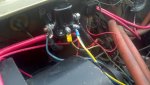
is there a number on your green wire?
 
thanks! This is tremendously helpful but unfortunately I'm working with a pretty severe case of po. The wires going to the coil were so badly damaged I wound up replacing the green and white wires that were there with a new 16 gauge yellow and blue wire (what I had on hand). The wires look similar but I'm not 100% positive if anybody knows exactly what those should be.

After clearing out some wiring that dead ended (missing accessories?) and removing some heat shrink here is what I'm looking at. I had (originally) three white wires, two green wires, the blue 10 gauge, the 2 gauge going to the common post on the switch and another 2 guage to the starter motor. The two white wires that go to the cab I connected to the "s" post, the white and green wires (now replaced by blue and yellow) met with a red wire and connected to the coil. The blue 10 gauge I connected to the left post (after realizing the ignition wouldn't work without it) and I didn't have the green wire to the alternator connected. This allowed the ignition to work properly and the vehicle to start, but the idle sounded terrible!

So down to the brass tax. It sounds ike the green alternator wire is supposed to hook up on the same post as the blue 10 gauge, but is there anything else that seems to be missing? The copper post is getting really beat up from all the different variations I've tried so I'd like to make this next attempt my last one. Thanks for all the support and I'll keep slugging away at cleaning up the rats nest under the hood.

Ok let start with:
It sounds ike the green alternator wire is supposed to hook up on the same post as the blue 10 gauge
I pretty sure your right, that same post also has bat + coming from bat switch.

I guess I am going to have to cut into my harness to verify that green wire my eye sight is not what it used to be and neither is the wire numbers for that matter.
Blurblur can you explain whitch side of your solenoid is the starter side, I can't tell from the pic, it makes a difference on my preception of what I am looking at.

I do see what looks like 2 wires on the solenoid small post where your white wire is. Looks black, that post only needs a system ground which should be white. You can verify with a volt meter.

I am going to have to cut into my harness to be more detailed but then it May not be what you have under your hood with the po virus you describe. If you were here it would be no problem.

Give me untill this weekend I will see if I can come up with a complete diagram, but you need to figure how to put it in your truck I can't sort through the po virus from here, sorry.

Craig, I will include the isolator in that to, although the surefire instructions have a good drawing too.

I will be back when I have a little more time, I know you what to get it done, I know how you feel.

Ron
 
Absolutely no rush ron. I bought a marine grade 12 circuit fuse panel so pulling out all the accesories and re-routing them was in the plan anyway. I'm thinking the more I pick through the more clear what my solenoid issue is should be. My buddy is also coming up to give me a hand too so as I figure things out I'll post. Thanks so much again ron.

Edit:

"blurblur can you explain whitch side of your solenoid is the starter side, I can't tell from the pic, it makes a difference on my preception of what I am looking at."

sure thing. As you're facing the solenoid:

left post: this has the 2 guage wire going to the common post on the marine switch, the blue 10 guage that goes to the bulkhead (I'm assuming that meets up with the blue 10 gauge at the alternator somewhere) and now the green wire that comes directly from the alternator.

Middle left post: all I have here is the two white wires that go to the bulkhead (and I assume the ignition). There is a third white wire that goes to the coil...maybe I should swap that in and one of the others out?

Middle right post: here I have a blue and yellow wire. This used to be a white wire and a green wire but they were in really bad shape so I flat out replaced them. Both of these along with another red wire go to the coil.

Right post: all I have here is a 2 gauge black wire that goes to the starter. The starter is bridged like it should be.

Again, it starts, runs, and turns off with the ignition switch like it's supposed to. The only problem is the idle sounds like there is some serious misfiring going on. I'm guessing it has to due with the wiring around the coil?
 
Last edited:
Back
Top