Cam bearings are removed with the same tool that is used to install 'em. They are driven out to the rear (one at a time), just like when doing the install except you aren't concerned with the depth/alignment issue, just drive 'em on out the back of each bearing saddle. Here's the tool/instructions I have:
http://www.lislecorp.com/uploads/instructions/18000_webinstr_cc56dd9726db5.pdf
For an engine stand, the typical chinee 1,000lb. Stand sold by most auto parts stores, harbor freight, etc. Is just fine. However, you will have to fab an extension for one of the mounting arms in order to span the ihc block bolt pattern on the rear of the sv or I-4 engines. Don't try and get by with just three mounts attached.
Hf has those sometimes for $39.95, I have three of 'em plus one or two others that are similar but came from other sources.
I now simply set a bare block on a large "box" made from 2x12 for knocking in bearings and douching all the oil galleries so I can access all points from both front and rear. With an engine stand you have to demount a block to comfortably access all the cleanout points. I knock the cam bearings in while the block is on the box, then remount on the engine stand to complete.
The babbit layer of that type bearing is very soft. The bearing can be totally destroyed yet the finish on the cam journal not be affected at all. But each journal must be checked for "roundness" and surface finish of course.
The "saddle" in the block for the cam bearings to seat in must be the correct diameter also, otherwise a bearing will spin. The nature of these engines is to not spin a cam bearing, since the bearing material disintegrates well before the bearing May try and seize to the journal as the cam rotates.
Your oil delivery test would indicate only that #2 and #4 cam bearings are serviceable (maybe), the rear cam bearing (#5) is the one that is critical for oil delivery to the lifter gallery. #3 is just..."a bearing" and #1 controls oil delivery to the cam/crank/distributor gears. The only way to determine bearing condition is to do a visual inspection. That can be done by simply removing the cam (carefully!!) from the front of the engine without pulling the heads. You will need to inspect each bearing, front-to-rear very closely with a strong light, any surface deterioration will be very apparent.
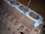
When installing the bearings in a shortblock I use the drill bit or a suitable dowel for verifying alignment. Since the oil port in the head is "offset" from the corresponding oil port in the block, you can't simply look down through the orifice or run a wire or drill bit through. The head gasket has an oval seal area at the port junction to seal the oil path through that offset.
I have several pics of cam bearing installation, along with modding the oil delivery port area for the #5 bearing in order to "un-restrict" the oil supply to the lifter gallery I can post when you need 'em.
There is no windage tray used on these engines...removing the intake manifold really doesn't allow any better view of oil port alignment or cam bearing finish since the casting is solid except for the knock-outs used for oil drainback at each end of the lifter chamber.
This pic shows how I use the aircraft drill bit with a drill stop collar to "align" the oil hole for #2 and #4 if it needs to be corrected. That also involves using a micro die grinder inside the bearing to chamfer the hole in new bearing before sticking the cam in. One more reason to not do this with an engine block installed in the vehicle! Notice the opening in the head gasket I mentioned. The head gasket was placed on this block in order to illustrate this process, the block was in very early stages of cleanup and has not yet been honed nor gone through the final cleaning process.