Scout II 727 Output Shaft Conversion

Continuing on...

Here we see the insides of the oil pump, no issues found here and the clearances all check out ok.

The inner rotor is a pressed metal part and therefore is very brittle. Those two drive tangs are what breaks off inside if ya just push the torque converter into position without properly aligning.
 

Attachments

  • Pump rotor_gear.jpg
    Pump rotor_gear.jpg
    63.5 KB · Views: 877
This is the completed oil pump after the replacement front seal was installed. In this shot ya see the two new sealing rings slathered with transemble. This is done to prepare the temporary assembly for checking the clutch pak actuation.
 

Attachments

  • Pump complete.jpg
    Pump complete.jpg
    53.2 KB · Views: 979
With the pump assembly upside down on the gurney, the clutch set is slid into place just as if it's installed inside the case.

Then using compressed air throttled back to 25psi with the regulator, pressure is applied to the front and rear oil feeds to the clutch pistons in turn. We listen for a definite "thud" when the piston actuates, that means the clutch will apply and then retract as it's supposed to. Normally, if a clutch does not apply, that means one of the rubber sealing rings was damaged during assembly.

This test will be repeated later in the assembly process.
 

Attachments

  • Clutch pressure check.jpg
    Clutch pressure check.jpg
    66.1 KB · Views: 865
Since both clutches passed the test, the set was then installed in the case. This can be a bit tedious also as all the clutch disc splines must be aligned with their driven gear in the planetary assembly. Sometimes it's a struggle, sometimes they literally fall right in the hole. Today was gift!

Here's the front (kickdown) band after coming out of the atf pre-soak, along with the adjuster anchor and the apply strut. This is a premium band, a so-called "flex" version though it is not a double-wrap as used in drag race units.
 

Attachments

  • Kickdown band parts.jpg
    Kickdown band parts.jpg
    56 KB · Views: 939
Before installing the band assembly, we verify that the clutch set is completely engaged with the planetary drive shell. After ya do a few of these assemblies you come to know what to look for here, since this trans had run for many hours, there is a definite wear pattern on the shell legs, so we just make sure that the wear patterns line up.

If the clutch set is not all the way back, then when the pump is installed and the bolts tightened, there will be no end play to the input shaft, again, that would result in binding when the trans tried to engage and disastrous results!
 

Attachments

  • Clutch assembly engaged.jpg
    Clutch assembly engaged.jpg
    60.6 KB · Views: 890
Now we're gonna make another mod that is part of the B&M-supplied upgrade kit. This is a high ratio band apply lever.

This item transmits the action of the servo piston to a "clamping" action of the band around the front clutch drum when the hydraulic signal is applied.

The oem lever has an apply ratio of 2.8. That is a very common lever, though some versions of chrysler apps used various other apply ratios.

The B&M replacement lever has a ratio of 5.0! So that increase in lever apply force, combined with the enhanced friction characteristics of the premium band material, give us a significantly load capacity. And all that stuff is engineered to work with the B&M reprogramming of the valve body.

So first we're gonna remove and discard the oem lever.
 

Attachments

  • Kickdown servo lever compare.jpg
    Kickdown servo lever compare.jpg
    62.9 KB · Views: 1,055
Looking inside the bellhousing, we see a internal wrenching pipe plug. Using a 1/4" drive socket extension, we remove that plug, clean it, and then prep it for reinstall by wrapping with teflon tape.
 

Attachments

  • Servo lever retainer plug remove.jpg
    Servo lever retainer plug remove.jpg
    65.9 KB · Views: 933
Using a magnet, the pivot shaft is extracted just far enough to allow removal of the apply lever.
 

Attachments

  • Servo lever pivot remove.jpg
    Servo lever pivot remove.jpg
    74 KB · Views: 906
Here's the two levers side-by-side.

You can clearly see the "2.8" (looks like a 2.9 don't it?) ratio stamped on the oem part. The B&M lever also has "5.0" stamped on it for identification.
 

Attachments

  • Servo lever compare.jpg
    Servo lever compare.jpg
    72.4 KB · Views: 940
Last edited:
Part of the overhaul process involves removing the accumulator and servo pistons and renewing sealing elements on all. That has been done along with an additional piston modification using a B&M component. That is easier to do with the servo levers (kickdown and low/reverse) removed from the case.

Once the levers are back in position, then the kickdown band goes in and the adjuster and actuator strut engaged. Here ya see the band installed and wrapped around the drum, the notch on the band anchor on each end point forward. It is possible to get the band in backward, but it will bind the drum when the oil pump is installed.
 

Attachments

  • Kickdown band install.jpg
    Kickdown band install.jpg
    73.1 KB · Views: 1,404
Now we stick the pump in the hole. It's already been prepped, a fresh gasket installed in the case, and the perimeter "o" ring has also been renewed and greased with transemble.

Two homebrew alignment studs have been installed in the case to guide the pump into position. Once it enters the seal area, it's impossible to move it laterally, so the line-up studs are imperative.

A few light taps with a soft-face hammer drive the pump home, it should never be drawn in using the retaining bolts!

All the pump bolts were replaced since the previous builder had butchered 'em, new rubber-coated sealing washers for each bolt are included in a soft parts kit.
 

Attachments

  • Pump in position.jpg
    Pump in position.jpg
    71.9 KB · Views: 995
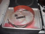
After the pump is tightened down, then we adjust the bands.

I'm not going to call out the band adjustment spec for this B&M parts build, the values they specify are only for use with the parts included in this kit!!! Do not use the oem band tension specs or any other spec from any other parts supplier!!!!

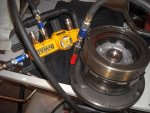
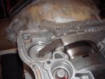
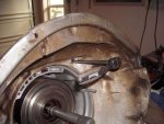
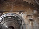
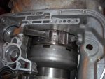
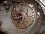
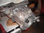
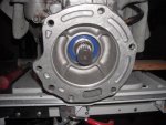
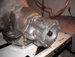
Now we're ready to test the servo actions and do a final test of the clutch pack since the pump body is in place. To do that, we use the soft-tip blow gun again with a regulated pressure of 25psi. I've marked the four pressure ports on the case that we're going to probe with the air.

The two in the front rail are for the front and rear clutches. So we apply air to each port in turn and listen for the clutch "thunk" again.

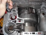
Then we go to the marked ports on the side of the case, those are the apply ports for the servos. When pressure is applied, either the front or the rear servo will actuate.

If....both clutches operate correctly, and both servos operate correctly, then if the valve body is correctly assembled and the bands are right, this unit will shift as it should!

When doing diagnostics on a suspected failed transmission and it's still installed in the vehicle, you can remove the valve body and perform these same four tests from underneath. That does not tell ya whether or not the frictions are any good, but it does tell ya if the bands and clutches will apply.
 

Attachments

  • Servo pressure test.jpg
    Servo pressure test.jpg
    76.6 KB · Views: 964
We're gettin' close now...next up is to clean/inspect and prep the governor assembly for installation.

This has to be done in a sterile manner! We can't have anything floating around in the oil that will cause any governor component to stick. And the governor assembly gets douched with a spray lubricant just before it's slid into position on the output shaft.

Here ya see the two sealing rings have been replaced and doped. In the case of this governor, the previous builder had re-used one of the old rings (it was totally worn out!!) and had used the wrong ring in the other position, it was too large!
 

Attachments

  • Governor assembly install.jpg
    Governor assembly install.jpg
    73.3 KB · Views: 1,000
Here's the governor assembly after it's installed on the output shaft and the seal rings engaged inside the rear drum support. The parking gear is bolted to the governor, when "park" is engaged on the control lever, a spring-loaded pawl mounted in the tailhousing drops into one of the slots on the gear and prevents shaft rotation.

Notice the snap ring just behind the governor assembly. That item is critical to overall endplay of the output shaft assembly. If this output shaft was for a Scout II, then it would have only the single snap ring.

But...this conversion is for the Jeep output shaft and it does not use a bull gear to drive the transfer case. Since the original d300 (and soon-to-be klune) uses a splined coupling that kinda "floats" in there, a second double thickness snap ring is used on the output shaft to act as a thrust surface against the new bearing in the tailhousing. Good thing I found that buried in the parts stash, I don't know where I'd find one locally!
 

Attachments

  • Governor complete.jpg
    Governor complete.jpg
    69.6 KB · Views: 931
So now, we see what this has all been about.

The tailhousing has been temporarily installed with a gasket and two bolts to check the endplay of the output shaft. We can't have any bind at this point, that would be a major issue!

This one checks out just fine! So the snap ring is the proper dimension. The rest of the bolts were installed and torqued in place.

The gaskets I use are "universal" versions, once the unit is complete, I'll trim the excess material.
 

Attachments

  • Tailhouse install.jpg
    Tailhouse install.jpg
    64.4 KB · Views: 854
And here's the bizznizz end of the deal where the klune's gonna live.

Hopefully the seal that goes on this side of the bearing will be here tomorrow afternoon and it'll get knocked into position.

Then the inside of this housing will be sprayed with an anti-corrosion inhibitor before the klune is mated. This space does not need to be vented since it's dry.

All that's left at this point is completing the B&M-modded valve body, installing same, and then mounting the pan. Once that's done it will get a final exterior pressure washing to prep for paint or whatever jen wants to do with it going forward. So we'll have one more update tomorrow.
 

Attachments

  • Jeep output shaft complete.jpg
    Jeep output shaft complete.jpg
    66.3 KB · Views: 834
Here's the completed build.

I screwed up in trying to locate the correct seal for the output shaft-to-klune input coupler, working from an incorrect dimension on my part. So terry has located the correct seal and he can handle that detail.

The exterior of the case will be sterilized tomorrow and then loaded out for delivery.

The other half of this story is found in this thread:

http://www.forums.IHPartsAmerica.com/I-h-s-t-o/5432-girl-Scout-2-0-a.html
 

Attachments

  • Complete.jpg
    Complete.jpg
    69.8 KB · Views: 785
I didn't change the vent setup afterall. I had some concern about trying to salvage the hole that had been drilled out when that brass compression fitting was installed and didn't wanna risk either wasting the pump housing or end up with a leak at that point once I had sealed the hole.

So that copper tube vent will work ok, it's just ugly!

The Jeep/d300 adapter needs no vent like the Scout II setup had (which had in turn been plugged with a sheetmetal screw!). And I see the klune vent and the d20 vent setup you have fabbed so all three vents can be run into a catch can.

I've got some crc sp-400 corrosion inhibitor we'll coat the inside of the tailhouse and the nose of the klune with before mating the parts. And a tube of sealant to use on the surfaces before bolting together for the final time.

If you have the dimensions for the fasteners needed for the klune attachment, let me know. I have tons of grade 8 hardware here so I can pull out what's needed.

See yawl tomorrow!
 
Back
Top