The manual states on the 11" angle link clutch the clearance should be .320". I had a local clutch rebuilder rebuild my pressure plate and the clearance is only .210". Did they screw up or am I missing something? This was to be motor install day and this is the last item before install.


You are using an out of date browser. It may not display this or other websites correctly.
You should upgrade or use an alternative browser.
You should upgrade or use an alternative browser.
Pressure Plate to Flywheel Clearance
- Thread starter cheese1
- Start date
Come on guys I could really use the help here. Is the .320" the maximum allowance and anything less okay? Should the .210" be adjusted out? I took a day off on Friday to get this motor in and stopped when the clearance didn't check out. I'd hate to put the clutch in and install the motor to only find out I have to pull the clutch.
Michael Mayben
IHPA Tech Moderator - Retired & No Longer Online
I don't have an angle link clutch here for comparison.
After reviewing the service manual regarding this clutch, if the clearance is less than specification, I can see it's possible that there May not be enough travel/throw in the throwout system to allow the pressure plate to "release" completely without dragging.
The travel of the entire clutch release system has to "coordinate" with the travel of the pressure plate in order to create a clean release with no drag.
I'd return the pressure plate to the rebuilder along with the information in the service manual and have them verify and correct the clearance.
Did they actually replace the pressure plate itself in your original clutch cover...or did they "regrind" the pressure plate so that it's now "thinner"??
Michael Mayben
IHPA Tech Moderator - Retired & No Longer Online
the measurements that the manual states is unclear if that is with the flywheel/pressure plate assembly engaged or not engaged.
The original pressure plate was full of cracks. They replaced the pressure plate with a new one. The cover is still the original with new springs.
That's what I thought, that would be the "norm" for a rebuilder!
That "dimension a" is with the freshly remanned clutch cover bolted to the flywheel with no clutch disc in place and in the "released" mode...just like driving down the road. That way when the disc is mounted, the release specification will be correct for the "throwout" travel, and provide plenty "lift off" of the pressure plate when released and not create any drag.
Your clutch builder May need to machine down the replacement pressure plate to achieve the spec. And take the flywheel also so they will have a reference if they don't have a test jig (they should have a test plate to verify any rebuilt clutch cover assembly).
This is a great issue to work on here in the forum, no doubt something that is often overlooked when having this stuff remanned due to lack of availability of new parts. I'm taking a clutch assembly over to our local friction materials remanner today...I trust 'em to do it right but ya just never know! The youngest guy that works in the shop there has been with the company for 21 years!!
So as I follow it if the flywheel, clutch disc, and pressurre plate are bolted together the part "b" measurement (flywheel to release fingers) should be within spec. The manual states 2.0"
the reason I am so worked up about the clutch measurements is I've read so many threads about clutches that don't release I figured some of the rebuilds are not measured for proper clearance.
the reason I am so worked up about the clutch measurements is I've read so many threads about clutches that don't release I figured some of the rebuilds are not measured for proper clearance.
Michael Mayben
IHPA Tech Moderator - Retired & No Longer Online
so as I follow it if the flywheel, clutch disc, and pressurre plate are bolted together the part "b" measurement (flywheel to release fingers) should be within spec. The manual states 2.0"
the reason I am so worked up about the clutch measurements is I've read so many threads about clutches that don't release I figured some of the rebuilds are not measured for proper clearance.
Exactly! Ya don't want to have to keep screwin' with the clutch and release!
I just got back form the supplier that does all our friction material relines, most of their bizz is superduty clutches for the timber and trucking industry.
The counterdude who is older than me, said the same thing about the pressure plate, they "adjust" it when rebuilding by cutting down the replacement item, since in many cases, they can no longer obtain the plates in varying "thicknesses", so they stock one thickness and grind to match. Then one of the machinists that actually does the work came out from the shop and confirmed the same for me. I've had them do two clutches for Scout 80 apps, but neither were angle link versions. They told me the angle link clutches are much more difficult to deal with in the rebuild process.
Is there a way to measure the proper clearance(s) on clutch rebuilds that someone such as myself or any other shade tree Scout guy can make before a install?
I can understand the measurement of the pressure plate to flywheel with the disc loaded, meaning as if the clutch is engaged. The more critical measurement I believe is the flywheel to release fingers. When the assembly is installed if the clearance is not correct the linkage adjustments are not infinite, you can only adjust in /out so much.
I try to be as meticulous as I can before installing parts. I was taught old school, measure twice cut once. I hate to go through the effort of doing something only having to do it again because somone else screwed up.
Here's some food for thought, and feel free to check with a higher/knowledgeable authority.
I believe that dimension "a" is for disassembly and setup, not a clearance per se. If you are using the same manual I've got, cts-2518, in the assembly section it states to use spacers of a given thickness or a spec'd tool number under the pressure plate before it's bolted to a surface plate. From there once it's bolted down, the release fingers are adjusted to the specified height. I see this as getting the finger height while the clamping pressure is on.
In the clutch specifications chart under "lever setting data" it lists the dimension "a" and the required spacer or tool number.
In another service manual, cts-2039-a, and the section I'm quoting covers a different style of clutch but the same procedure, it reads: "select spacers of proper thickness from se-2068 spacer plate set and place the three spacers at equal distance under the pressure plate, fig 7. See specifications for the the spacer plate requirement." again dim. "a"
so once the clutch is bolted to a jig or flywheel with the right spacer, then The release finger height can be attained. The adjustment has a finite range, so right along with what Mike said about the rebuild shop; the pressure plate has to "fit" the application.
One of the confusing things with IH service manuals is the information that is similar to procedures that are the same for different styles of components does not always carry over to each component or succeeding manual edition.
If I were building this clutch, that's how I would do it.
It May be that what you are measuring is the clutch in it's relaxed State. But if it's been since readjusted, who knows.
If this is beerthirty b.s.; let me know.
Last edited:
Robert Kenney
Super Moderator
Yep greg you are correct!!
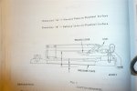
The proper way to set up a coil spring adjustable pressure plate is to mount the pressure plate assembly to a flat surface or a flat flywheel with the specified spacer with a thickness = to dim a between the flywheel and the pressure plate. Then set each lever via the adjustment screw and locknut so the distance from the lever tip where the through out bearing presses and the flywheel surface is = to dim "b". I get them as close as possible to the same measurment. A high or low lever can cause the clutch to shudder.
Have done many of this type and they all work great.
No way to set up one of these in a free state. They must be mounted, loaded and, set.
Pix for referance only. May not be correct for your application.
Ps
all beerthirth bs is good.