

You are using an out of date browser. It may not display this or other websites correctly.
You should upgrade or use an alternative browser.
You should upgrade or use an alternative browser.
Engine Cooling Systems and Components
- Thread starter Michael Mayben
- Start date
Craig
Active member
Thanks guys, I talked with a water pump re-builder that specializes in IH water pumps out of az. He said that running it at .015 is a bit tight, and if the bearing wears in or starts to fail the impeller will hit the pump body. As for the stamp vs cast he said the stamped has better flow "volumetric efficiency" I asked if he measured this and he said no, but pointed out the paddle size difference and open design between the two. He went over other items like engine timing, t-stat, fin counts, row counts, fan blade numbers and pitch, shroud, pressure cap, etc. Obviously passionate about IH junk iron too. He even mention using the fel-pro gasket as its thinner than what comes with a rebuilt pump. He said I could move it closer, but that would affect pressure more than volume, unless I was way out of spec. He said the pumps don't really get going until about 1,000 rpm's. So long idle times can cause some over heat issues too. He did mention that if there is a restriction within the system it could cause the impeller to just "slip" and not pump anything. [ I.e. Plugged up radiator] He said I could use a bearing splitter to grab and lift the impeller a bit and see if that helps any.
My plan right now is to get a baseline on the pump volume before changing the pump clearance. Take a 5 gallon pal and mount it where the radiator was. (yes I have room) plumb the bottom of the pal into the lower radiator hose. The top of the pal will be level with the upper radiator hose on the neck of the motor. With the t-stat removed and the by pass hose clamped shut I will spin the pump at full drill speed and see how fast I can fill another 5 gal pail.
Front of Scout
Attachments
Craig
Active member
Had to teach a class tonight so no testing, got some items ready. I sure hope the pump been out of spec is my issue. I did a lot of reading today and found that other pump manufacures are running there impeller that tight too. Some are even adjustable an you use a dial indicator.
Well .015" is a 1/64", and that's pretty damn loose compared to some of the pumps I work with. Believe me, at that clearance by the time the impeller crashes the volute it'd be s*** on yore haid 'cause it woulda told ya long before. I'd also check that bypass too while everything is down.
Craig
Active member
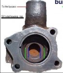
The pump re-builder yesterday said IH had at least 3 different by-passes. Not counting the odd-ball 1980 version. He said the size of the hole in the center of the casting was different. So IH must have been fiddling with different designs over the years too. Michael posted this real good pic some years ago, I added the burp hole arrow ") but mine is in good shape.
but mine is in good shape.

but mine is in good shape. Michael Mayben
IHPA Tech Moderator - Retired & No Longer Online
That's an interesting observation on the part of the pump rebuilder Craig! I'd sure like to see some documentation regarding that. I've checked out many of the tstat housing, many of which are rotten beyond service, but never recorded any "differences" in the bypass hole, though many of 'em are badly rotted away in that spot.
I do know that there are some different part numbers for the same basic component, but I "think" that is because of the various locations for the heater hose nipple port (I have at least three different samples of that now), whether the app was an I-4 engine or sv (interchange except for the nipple port location), and whether it actually had a tapped hole at all for the nipple (blank). Those are the "differences" I've observed but I'm sure I've not seen 'em all! Emissions motors in some platforms used a temp-control vacuum switch in that port instead of a heater nipple.
Mike Ismail and I also discussed this similar thing a few years back when he was working onna prototype "re-located" thermostat housing to go with the beer can manifolds.
Jeff also has a pile of these parts so maybe he can check 'em out by part number and look for differences in the bypass "hole" diameter?
My personal opinion on this same subject...the "change" IH made on the 345 for the mid-'79>'80 sii application was a simple "cost reduction" for a vehicle they knew was on it's death bed. Why take a highly engineered thermo-control system which was a major design issue in the reputation for longevity/durability for these engines, and then shitcan it after 25 years?? That made the cooling system no different than any chryfordrolet
many engines (other than IH) use all sorts of "tricks" internally in the coolant passages such as inserted "baffles", chunks of rubber hose stuck in critical locations, metallic "orifices", etc. To tweek and serve as workarounds for specific engine/platform spot engine cooling issues. Same for the cylinder heads.
IH did the same for the "ic" version of the 392 to address a specific issue regarding the use of that engine in medium duty platforms operated at continuous "max load/elevated rpm" conditions such as a fully loaded school bus. That was an evolutionary development for that specific engine due to bore size/bore center/casting wall thickness control and since the majority of those engines went into mainstream trucks and not into "light line" platforms, then the over-riding consideration was to reduce warranty costs on the medium duty stuff. That in turn trickled down into light line apps.
I've attached two here that I developed regarding this subject. That was enclosed with the rs 370-1xx thermostat kits I assembled a few years back and marketed as a fund raiser for our club. Those are no longer available, so I don't mind sharing the doc. Beware...they are large! This is information that was never addressed in any IH service publication.
Attachments
Craig
Active member
Craig
Active member
So I connected the bucket in place of the radiator and tested the pump, watching the flow, there was just a trickle. I raised the bucket 2-3" to get level with the output. That helped and I was getting a little flow. I then tried to pull the impeller up with a power steering puller, it would not move. So I bent the impeller fins up with a screw driver. I took care to lift from the inside so the whole blade would be lifted. I then used a dial indicator to check run out. It was a pain, but I got it looking good. The problem is you add the gasket and that moves it out a 1/32 or so. But I put it back on and tested it and saw a bit more flow, not a lot more look close to doubled, but not like what I expected. Then I figured out my drill is only 850 rpm, with a 2.1to1 reducing going to the water pump put me at like 389 rpm's  I guess I was in a hurry and being a 100 degrees outside did not help with patience either. But bending the blades up did help.
Edit. I just got the video uploaded and its hard to much change, but it looked more to me from my angle. Too bad I did not have a way to spin the pump at 1,000 rpm to see what would come out.
youtube - water pump test
Edit. I just got the video uploaded and its hard to much change, but it looked more to me from my angle. Too bad I did not have a way to spin the pump at 1,000 rpm to see what would come out.
youtube - water pump test
Last edited:
ihpartschad
IHPA General Manager
Put the belts on and start the motor.
Craig
Active member
put the belts on and start the motor.
Now that I see its not a fire hose type volume, that's not a bad idea. Thanks!! Not sure were my head was last night. I guess I was just frustrated with the power steering puller.
Just a note: I had to lightly sand the ps puller to get it to fit tight into the water pump groove. Where I made my mistake was there is a little space between the two halves that clamp around the impeller and when I used a pulley puller
 on it they leaned in and it shear off a tiny bit off the water pump. I put some shims in there but to late
 also I had to drill a small divot in the center of the shaft to keep the puller in the center. I used a carbide bit as the shaft is very hard.
 Ok tonight. ( amazing I'm getting like an hour or two each day to work on it
 )
) hopefully the new water pump gaskets arrive, I order 3 since there cheap. Measure the thickness for future reference. need to decide if I should factor the gasket into the measurement, as the manual is not clear on that. Do the clay test and see where I stand with a new gasket.
But first I will put the belts on and fire it up and see what volume I get at idle. It's very hard to get all the blades the same, but there all within a few thousandths I suspect even a new blade is not much closer then that.
Michael Mayben
IHPA Tech Moderator - Retired & No Longer Online
As for "setting" impeller-to-volute (pump housing) clearance...have you reviewed the water pump rebuild section in a service manual? Involves the use of press jigs made for that purpose in "adjusting" the impeller position to each application. And those current pumps with the serrated pump shaft are a one-shot item, ya can't "move" the impeller without destroying the press fit.
Water pump gaskets are the easiest to make...I keep 'em hanging on the wall, just gave out a few this past week! I make 'em in several different thickness using the same fiber/rubber composite material I use for the custom-cut tstat/neck gaskets. And no sealant of any type should ever be used on that gasket, if the surfaces are in good shape there is no need for any type sealant! You should see some of the shit I work on that has the pump vanes and volute filled with cured rtv, same for the tstat housings! That shit should be banned from the planet.
Since a gasket must be used in final assembly, then the clearance should reflect that installation. Personally, I don't see the clearance being that critical as long as it does not interfere. Yes, that shitball napa pump you started with is useless! But 0.015", 0.020", 0.025"?? That pump flow spec potential is much more than engine/heat exchange demand on these engines! They are not difficult or problematic to cool, the thermostat arrangement used guaranteed that fact!
But certainly if ya just simply replace a water pump with a service part, and had no cooling issue prior to the replacement, and then ya do have an issue, the pump is the most likely suspect due to poor quality control on the part of the manufacturer. Otherwise, the radiator is the most suspect always. It's "condition" changes inna dynamic mode and they are not lifetime items! Sure they can be serviced...put there are practical limits to what can be done with 30>50 year old crap! And those "high efficiency" (read a fin count so high air cannot hardly pass through), four core (again air cannot pass if the fin pitch was not reduced below prolly 10 fpi), and unshrouded units cannot create needed heat exchange in a real world app, but maybe they do meet some spec on paper!
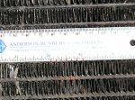
Your pitch shown of 12 fpi is normal for an oem radiator and is a tradeoff that allows adequate air flow with up to three rows, even more if the cores were designed with "offset".
As for the tstat housing pics that you referenced originally...those are not "my" pics! Those were part of a collaboration between john donnelly and doug shailor a few years back in a binder bulletin "newsletter" (electronic) article. That was published before the blowup between the two of 'em that resulted in doug getting the boot.
The doc I wrote had nothing to do with that deal, it's a "service" procedure which explains the detail of what to do especially regarding a neglected system. And it was never posted or discussed on the bb other than as an "offer" to send to folks who requested it by backchannel email. They never even identified the importance of the spit hole and overlooked several other areas that should have been pointed out. But...that's the bb!!
So consequently, I've never seen that housing in the bb pic, and neither jd or doug provides documentation or p/n for it for verification. None of the many housings I've delt with had that size hole (whatever it is), even though I've seen at least three different p/n units when servicing many various engines/rigs over the years.
Water pump gaskets are the easiest to make...I keep 'em hanging on the wall, just gave out a few this past week! I make 'em in several different thickness using the same fiber/rubber composite material I use for the custom-cut tstat/neck gaskets. And no sealant of any type should ever be used on that gasket, if the surfaces are in good shape there is no need for any type sealant! You should see some of the shit I work on that has the pump vanes and volute filled with cured rtv, same for the tstat housings! That shit should be banned from the planet.
Since a gasket must be used in final assembly, then the clearance should reflect that installation. Personally, I don't see the clearance being that critical as long as it does not interfere. Yes, that shitball napa pump you started with is useless! But 0.015", 0.020", 0.025"?? That pump flow spec potential is much more than engine/heat exchange demand on these engines! They are not difficult or problematic to cool, the thermostat arrangement used guaranteed that fact!
But certainly if ya just simply replace a water pump with a service part, and had no cooling issue prior to the replacement, and then ya do have an issue, the pump is the most likely suspect due to poor quality control on the part of the manufacturer. Otherwise, the radiator is the most suspect always. It's "condition" changes inna dynamic mode and they are not lifetime items! Sure they can be serviced...put there are practical limits to what can be done with 30>50 year old crap! And those "high efficiency" (read a fin count so high air cannot hardly pass through), four core (again air cannot pass if the fin pitch was not reduced below prolly 10 fpi), and unshrouded units cannot create needed heat exchange in a real world app, but maybe they do meet some spec on paper!
Your pitch shown of 12 fpi is normal for an oem radiator and is a tradeoff that allows adequate air flow with up to three rows, even more if the cores were designed with "offset".
As for the tstat housing pics that you referenced originally...those are not "my" pics! Those were part of a collaboration between john donnelly and doug shailor a few years back in a binder bulletin "newsletter" (electronic) article. That was published before the blowup between the two of 'em that resulted in doug getting the boot.
The doc I wrote had nothing to do with that deal, it's a "service" procedure which explains the detail of what to do especially regarding a neglected system. And it was never posted or discussed on the bb other than as an "offer" to send to folks who requested it by backchannel email. They never even identified the importance of the spit hole and overlooked several other areas that should have been pointed out. But...that's the bb!!
So consequently, I've never seen that housing in the bb pic, and neither jd or doug provides documentation or p/n for it for verification. None of the many housings I've delt with had that size hole (whatever it is), even though I've seen at least three different p/n units when servicing many various engines/rigs over the years.
Michael Mayben
IHPA Tech Moderator - Retired & No Longer Online
I "think" the pics were actually done by jd, but don't know how they managed to get along to actually write the text! That's why the pics survived the purge! But some of the pics May have been provided by doug to him privately. That "article" was only available to supporting members, it was only a few months back when this same old "thermotstat" subject came up yet again, that jd "unlocked the info and made available to the great unwashed.
One more chikinshit bb deal in my book. Doug is a curmudgeon like me, but if he's wrong about something, then he'll do the research and prove fact, right or wrong! And then correct his position. Still does, we communicate onna as-need basis!
One more chikinshit bb deal in my book. Doug is a curmudgeon like me, but if he's wrong about something, then he'll do the research and prove fact, right or wrong! And then correct his position. Still does, we communicate onna as-need basis!
BScoutII
Member
Craig, thanks for the pm. I had, along w/rock tractor came to pretty much the same conclusion. It had to be the water pump creating the cooling system problem. I really appreciate you photos and will take a close look at them soon. My water pump is comming out within a week or so and I'll try bending the blades at that time.
Craig
Active member
Is that you randy? The changes to the pump blades did increase flow. I drove it with the electric fan last night and it got warm 220 in just a few miles, I switched over to the fixed fan this morning and it runs a bit cooler on the freeway, but its cooler outside right now. It runs warmmer in town and does not cool off as fast as the electric when parked. To be expected as the electric is running a lot faster then idle. With the pump working better, my radiator is not showing as much of a drop in tempature. I'm thinking about getting my radiator re-cored. $300. New is like $450. Once it get hot outside I will do a complete ir heat test.
Randy do you have a stock radiator? Is it new?
Randy do you have a stock radiator? Is it new?
Craig: before you go spend'in a pile'o'money, remember what mayben 'sez; "it ain't broke from the faktry!" your whole issue started from a very poorly assembled pump, two of 'em from the looks of your posts. The .015" book clearance is critical, give or take a few. As I've posted, my 2 where around 15 to 20 or so thou, added to that the gasket and you'll get around a 32nd or so inch of actual Runn'in clearance. You started off with 2x that right outta the box going on the one picture. My day job involves these kinda pumps, they're used in hydronics, chill water sytems, tower cooling loops, and on one job we repaired a nuclear reactor coolant pump that was the same design with an open face impeller but just a whole lot bigger. That's a story in itself, but the end result was that going back to spec and a properly set up lube deal; the returned to spec performance warranted a letter of appreciation to our department head. The repair cost was less than half of what the rad. Dept. Expected to spend on a new one.
Engine coolant pumps for the most part are circulators. They ain't for head or discharge pressure, but flow; and flow in a closed loop system, where after going through the circuits and pressure drops the pump gets a positive suction or push on it's return or suction side. That's critical in an engine to order to keep it's suction above the vapor pressure or boiling point of the coolant it's pumping; otherwise there'll be cavitation and another set of problems. Yes with elevated operating system pressure that possibility is reduced, but it sometimes happens in engines with a return side thermostat as found in some asian/pacific cars. A lot of what I thought to be corrosion was from cavitation. Pumping from buckets doesn't really show how the pump will really work in a dynamic closed loop setup. Here's what I mean by slippage The impeller by centrifugal force of rotation slings the water from the center out to it's periphery; there the volute channels this water and converting the kinetic energy to potential, directs it to a discharge point, in our case 2. The water is always go'in the path of least resistance, if the runn'in clearance of the impeller is too wide, it's just gonna recirc back to the low pressure side or center of the impeller reducing capacity of the pump. Clearances are defined by the speed, diameter, specific gravity of the fluid, and so on. This ain't rocket science, close is good enough; not 3 to 4x. I could go on about curves, and how much drop off in flow is related to speed, let alone how much sloppy assembly can throw a pump off it's curve all together.
Just my .02, but I really think that to nail this cooling dilema is get a properly built to spec pump, a stock fan; and from there you can accurately decide if you're gonna need a radiator or not.
Lou
Member
Mike, Craig r., Craig, et al,
I’ve read this thread with great interest. Perhaps my quest has an end? I swapped out my factory original big nut pump in 1988 with 118,000 miles on it and went to a napa top hat when I couldn’t find a big nut clutch. Next pump was 1996 at 151,000 miles. Then 1998 at 162,500 miles. Then 2006 at 180,820. I’m now at 188,000 miles. I always sought out the sacred cast impellers. There were a few radiator replacements in there, went to a high efficiency (more tubes/fins) three row in 2002 and back to a stock three row in 2007.
My temperature issues first became noticeable to me about 6 years ago. In spite of much tinkering, and much help from Mike mayben and others, with many posts on the bb, I still have a truck that operates hotter than I think it’s design would indicate. This in spite of having become versed in, and a believer of all things related to balanced thermostats, fin counts, timing, jets, shrouds, high lock-up fan clutches and blade pitch and count.
This thread is the first thing that’s made sense to me as I’ve always believed in mikes mantra that they didn’t build these things broke. Greg r.s discussion of slippage yesterday was one of the most illustrative descriptions I’ve found thus far. Now I get why the clearance matters.
I see two courses. Keep buying new pumps until I find one with reasonable clearance or find some one to set up a custom one. That would be pricey. One thought: with a stamped impeller, could one weld a bead down the face of the impeller blade and grind it to spec? Redneck but simple.
Thanks again for the great discussion and information here.
Lou
75 Scout II, 345 auto.
Michael Mayben
IHPA Tech Moderator - Retired & No Longer Online
About time you showed up around here lou!
And tha dam yeller rig is still too h.o.t. For ya??
Tha jeffmiester and me been discussin' some ihon "custom" pump setups, ain't hard at all to do. I'll be snakin' some water pump housings for a sv from Jeff's pumppile when I'm down there in October to do the first one. May have one even sooner if I can talk some local boyz outta some housing so's I don't have ta pay shipping on them cast iron monsters. The pumps are no biggee, they are on the shelf up here everywhere. But I ain't gonna screw with the cast impeller stuff, that ain't "normal" these days and is of no use to me.
I have one "kinda" spare pump housing now (it don't actually belong to me), May use that one for a core to git started.
A custom "kit" would consist of a matched pump and pump housing, new water tubes, water tube "o" rings, etc., all painted up real purdee. Use an eight hole hub pump that can go either clutch or no clutch...I'm leanin' towards not using clutches anymore since big nut clutches are history and no one will pay for one anyway. Include the appropriate spacer to put the fan in the correct position in the shroud.
The aftermarket replacement hayden clutch could be used, but eliminating the clutch eliminates one more variable. Many folks are running replacement clutches right now that they bought because they were cheeep. But those are not thermo-control and end up inducing air flow problems that did not exist before replacement! And they don't even know it 'cause they bought "less expensive"!
In the real world (not the world of parts marketing spin), a fan clutch is good for maybe 1.5hp. And not even measurable fuel consumption difference on these tractor motors. Who cares about "reduced underhood noise" when yore drivin' a tin box with no sound insulation and no top??
Keep this in mind here...I believe you and me talked this squeeze before? The sv motors originally were set up to be cooled witha radiator capacity about 20% greater than an oem sii system. And then the "upgrade" woulda been the "hd" cooling option which included the three core rad, the big nut fan assembly, etc. Which could support both an a/c condenser and a tranny cooler. All an engineered package and setup for a gvwr of around 6klbs.
Take that same motor (304/345) and stick it inna sii...yeah it has a crossflow rad which is more efficient than a vertical unit. But so did the squarebody fullsize stuff. But the sii rad is about 20% smaller in overall size (and, the rig is lighter also). Add the same "hd" package...and the rig now has only marginal heat exchange capacity as compared to the vehicle design for which these motors were originally intended.
Point is, the sii cooling system from the factory is marginal in my opinion, either standard system or hd. Then start scruuin' with all the popular non-engineered workarounds, water jackets half plugged from no maintenance over 30 years of service, a radiator that will not pass a pressure test, a cap that will not meet spec, a recovery system that is either missing or non-func, no shroud, a clutch fan that won't go into lockup when it's supposed to, internally leaking head gasket(s), etc., etc.
Now I know this does not describe your rig, but I'm just trying to make a point that does describe the typical sii with "cooling issues" (not Craig's either!). And 90% of the time the only thing that's bs'd about is the "robertshaw thermostat". Yes, that is an essential component, but is not a root cause performance issue/deal maker!
Lou
Member
Hola Mike,
I've been lurking around the bb but having recently found jeffs new neighborhood I'll be moving over here.
I'd be real interested in a properly set up pump/housing for the Scout. I'd offer that I had some problems with the tubes awhile back, all posted on the bb. I had three sets, all with IH numbers where the drivers side tubes were all different lengths. On the shortest one the "o" ring sat right at the bevel. I also had to make new forks to hold the tubes in as the new ones only have a stamped flare instead of the old steel ring.
But I digress, (got it from you!). Put me down for this and thanks for all the great information and fact you guys work up.