Michael Mayben
IHPA Tech Moderator - Retired & No Longer Online
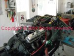
Quite often I help folks recover dead dawgs and IH junkiron. Stuff that ain't run in years. Sometimes the crap is not drivable as such, but we need to move it into a position to load onna trailer, etc.
Before attempting ta crank a motor that's been sitting, I always perform the procedure outlined and discussed in this thread, post #3:
http://www.forums.IHPartsAmerica.co...I-4-sv-engine-non-oiling-rocker-assembly.html
Once I'm certain the motor is pre-oiled, then comes the issue of the fuel and electrical systems. I have a collection of various carburetors (fresh ones) that can be used to swap on depending upon the engine and application needed. And a stand-alone fuel delivery system with dedicated electric fuel pump that the rig can be run from so I don't have to deal with the common fuel system deterioration issues on this stuff.
That leaves us with needing a functional electrical system, just enough to fire off the motor, no matter which engine we're dealing with, I-4, six-banger, or sv.
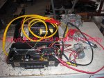
So I've whipped up an electrical system inna box that serves that purpose. A self-contained starting and ignition system (no battery charging capability at this point).
This shot is an example of the big picture...the electrical box, a typical "make run" carb for a 4v manifold, and a built distributor for an sv. If the rig I'm working with is an I-4, then the appropriate carb is substituted along with another distributor that is ready to run. The Holley electric fuel pump is shown as an example of how it interfaces with the electrical supply. I have several other types of electric fuel pumps (and regulators) that can be used when/if needed.
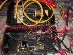
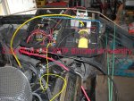
All this can be powered either from a jumper battery or the primary vehicle battery if it's serviceable, using the large alligator clamps. Both vehicle battery cables are disconnected and set aside. Then the engine starter is connected with a cable down to the battery stud on the vehicle starter solenoid, with a jumper attached to the "s" terminal, the vehicle battery positive cable is removed and insulated from ground if the vehicle battery is gonna be used. All other oem electrical connections are also removed from the starter solenoid and insulated from ground.
The ground cable from the box is then connected to the engine block. Depending upon which generator or alternator is mounted to the engine, all electrical connections are removed from the unit.
The replacement distributor (points unit) is installed and connected to the box through a dedicated circuit, and the electric choke b+ feed is also connected to the box. If the electric fuel pump is going to be used, then it's also connected to the box and is operated from a dedicated on/off switch on it's own fused circuit.
Before attempting ta crank a motor that's been sitting, I always perform the procedure outlined and discussed in this thread, post #3:
http://www.forums.IHPartsAmerica.co...I-4-sv-engine-non-oiling-rocker-assembly.html
Once I'm certain the motor is pre-oiled, then comes the issue of the fuel and electrical systems. I have a collection of various carburetors (fresh ones) that can be used to swap on depending upon the engine and application needed. And a stand-alone fuel delivery system with dedicated electric fuel pump that the rig can be run from so I don't have to deal with the common fuel system deterioration issues on this stuff.
That leaves us with needing a functional electrical system, just enough to fire off the motor, no matter which engine we're dealing with, I-4, six-banger, or sv.
So I've whipped up an electrical system inna box that serves that purpose. A self-contained starting and ignition system (no battery charging capability at this point).
This shot is an example of the big picture...the electrical box, a typical "make run" carb for a 4v manifold, and a built distributor for an sv. If the rig I'm working with is an I-4, then the appropriate carb is substituted along with another distributor that is ready to run. The Holley electric fuel pump is shown as an example of how it interfaces with the electrical supply. I have several other types of electric fuel pumps (and regulators) that can be used when/if needed.
All this can be powered either from a jumper battery or the primary vehicle battery if it's serviceable, using the large alligator clamps. Both vehicle battery cables are disconnected and set aside. Then the engine starter is connected with a cable down to the battery stud on the vehicle starter solenoid, with a jumper attached to the "s" terminal, the vehicle battery positive cable is removed and insulated from ground if the vehicle battery is gonna be used. All other oem electrical connections are also removed from the starter solenoid and insulated from ground.
The ground cable from the box is then connected to the engine block. Depending upon which generator or alternator is mounted to the engine, all electrical connections are removed from the unit.
The replacement distributor (points unit) is installed and connected to the box through a dedicated circuit, and the electric choke b+ feed is also connected to the box. If the electric fuel pump is going to be used, then it's also connected to the box and is operated from a dedicated on/off switch on it's own fused circuit.