Clutch Question

what I need are dimensions a & b that you see on page two. Page three is a list of specs for various clutches. Maybe someone can find the clutch I have in another service manual and send me the specs?

Hope you find your specifications. You do realize those dimensions are set with setup blocks? They're called "spacer blocks" on page 3 of the pdf you posted. The dimensions are set under compression of the clutch plate on the setup blocks so you have the proper pressure on the disc and the right amount of travel in the linkage to release it once it's installed on the flywheel.
 
Yup, dimensions a & b

hope you find your specifications. You do realize those dimensions are set with setup blocks? They're called "spacer blocks" on page 3 of the pdf you posted. The dimensions are set under compression of the clutch plate on the setup blocks so you have the proper pressure on the disc and the right amount of travel in the linkage to release it once it's installed on the flywheel.
 
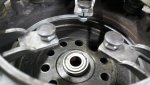
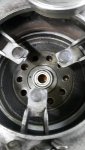
Yes, my thoughts as well. It always looked better with Mark 1 eyeball than the previous pics. Tried a little harder with these last pics

that looks a lot better than I thought it did in the first set of photos. Just have it resurfaced and you'll be good to go.
 
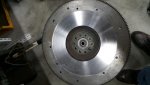
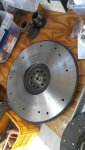
Back from machine shop. Little miscommunication..

It seems that the clutch is not affected


2016-05-11 18.51.06.jpg

2016-05-11 18.51.11.jpg

2016-05-11 18.51.47.jpg

2016-05-11 18.54.24.jpg

2016-05-11 18.51.57.jpg
 
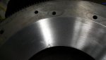
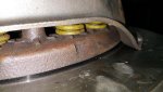
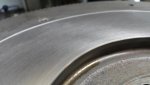
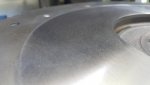
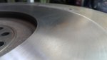
You need to send that flywheel back harry and have it completely surfaced. How it is now is wrong and throws the overall clutch adjustment off. IH's do not run a stepped flywheel like other cars/trucks so your machinist might be thinking that's the way it needs to be but he is wrong.
 
Is it bad to not be mirror smooth? I would think that one likes the extra friction of a surface that is not mirror smooth.

I looks like they cut it like a brake rotor instead of using a fly cutter. I brought it to a general shop that I do a lot of business with through my job. I will see if they can use a fly cutter this time. I was so surprised when they delivered like this, never seen a flywheel cut like this before

what Jeff said and tell the machinist to use a sharp bit in the lathe this time. :-]
 
It only needs to be rough enough to allow the new disk to seat, to rough and you'll wear a lot more clutch material off than necessary. It will eventually be mirror smooth, but to start with a surface that looks like it was sanded with 80 grit will do. The step Jeff pointed out is a bigger issue though as it will change the amount of pressure applied to the disk.
 
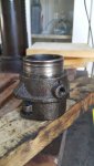
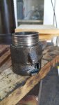
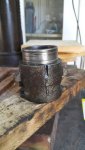
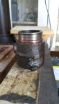
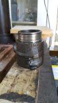
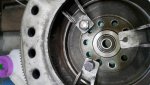
What do we think of this throw out bearing body? Iu am surprised that I didn't notice the wear two years ago, I was sure in a hurry at the time.

I realized that the only place the bearing has an interference fit is in the red area so the wear in the other areas shouldn't affect the bearing as the parts of the bearing that match the "non-red" areas are moving, so you don't want them to touch

2016-05-14 15.42.47.jpg

2016-05-14 15.42.41.jpg

2016-05-14 15.42.36.jpg

2016-05-14 15.42.30A.jpg

2016-05-14 15.42.30.jpg
 
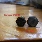
I am thinking about having the heads of standard 5/16-24 hex bolts ground down to imitate the stock clutch adjustment bolts.

However, the stock bolts have larger heads.

I could also ask my machinist if he could duplicate the stock bolt or at least one with an m8-1 thread which is closest to 5/6-24

View attachment gap adjuster_hex.pdf

2016-05-14 13.02.42.jpg

2016-05-14 13.02.54.jpg

2016-05-14 13.02.10.jpg
 
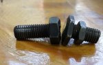
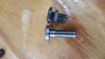
Got the flywheel back. I had them make me adjusting bolts. They look great but they made them m8x1 instead of 5/16-24, little communication mix up. They made me four of these and heat treated them, $20! I do a lot of business with them through work. They are making me a new set now

2016-05-22 16.14.21.jpg

2016-05-22 16.16.00.jpg

2016-05-22 16.15.50.jpg
 
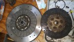
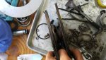
New friction plate came from IHPA, you can see that it was a good investment, mine was worn down considerably with at most 10 000 miles, more like 5 000

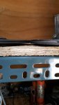
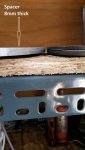
the last picture shows the new clutch next to the spacer I had made. The spacer is 8mm thick, the manual calls for 8.13, the millimeter equivalent to the english unit quoted. That makes for a 0.005" difference which I think I can ignore.

The interesting thing is that the spacer is thinner than the new friction plate and thicker than the old one which had a shiny rivet and therefore worn out. This makes sense, when I set it all up I'll bet that with the spacer in the adjuster bolts will be perpendicular to the spacer so that they'll start at an angle greater than 90 with the new friction plate, be at 90 at about the half life of the friction plate and a little less than 90 at the end of the friction plate life.

I'll report all of the measurements when I am done


2016-05-22 16.13.27.jpg

2016-05-22 16.13.50.jpg

2016-05-29 14.35.26.jpg

2016-05-29 14.37.35.jpg
 
Remember the disk will compress quite a bit when under the load of the pp.
The spacer spec is closer to the compressed thickness.
 
So I now have my custom made clutch arm adjustment screws cut the right size of 5/16-24. I bolted up the pressure plate to the flywheel with the spacer. I started installing the new screws when I began to suspect that they wouldn't go in enough.

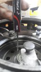
So I put in one of the old ones that I knew had the lock nut in the original position. Lo and behold the original will never work either if I go with 50.8mm specified for 11" clutches in the service manual. 52.37mm might work but I doubt it. Also the 1 15/16" for the 10.5" clutch wont work either. (see the pdf for these numbers) and yes, I know that I am measuring from the flywheel bolt surface and not the flywheel face, I added the difference to 50.8 to make the measurement you see in the picture

View attachment 07031601.PDF

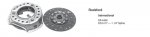
My clutch is not a bork & beck as it is listed at IHPA. It is a rockford clutch. I really need help finding out the settings of the adjuster screws

2016-07-02 18.38.35.jpg

2016-07-02 18.38.11.jpg

rockford clutch.jpg
 
The friction plate compresses about 10/1000" , 0.010"

I left the paper with the measurements back in my shop of course. I measured both the new and old friction plates while clamped in a c clamp and the 8.13mm spacer comes out at about halfway as I suspected

remember the disk will compress quite a bit when under the load of the pp.
The spacer spec is closer to the compressed thickness.
 
The finger height uses the flywheels machined friction surface as the datum, not the middle where the bolts go. Looks like you have the caliper on the middle surface in your photo. That will help your measurement.
 
Thanks Robert, I'm glad someone is watching the posts. If you look carefully above you will see that I know about the point where I should be measuring.

The distance from the flywheel bolt surface to the flywheel engaging surface was measured as 17mm, I added this to the 50.8mm specified distance

the finger height uses the flywheels machined friction surface as the datum, not the middle where the bolts go. Looks like you have the caliper on the middle surface in your photo. That will help your measurement.
 
ok. No one is sending me the dimension I need to set up the clutch. This would be the distance from the top of the screw heads to the flywheel face while a spacer is in place instead of a pressure plate and the pressure plate is bolted to the flywheel.

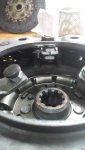
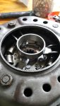
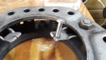
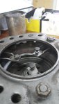
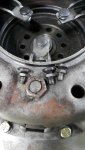
I measured the old bolts to get a sense of the original setup distance and attempted to match it. Notice that the space from jam nut to bolt head is variable, I checked that the clutch fingers have a similar variation. I gave the lower finger the larger distance.

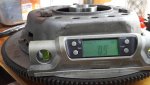
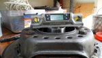
Then I made sure that all bolt heads are co planar so that the throw out bearing makes even contact.

So next weekend she's going back in there come hell or high water. I have sent a second email to mid-america clutch who sell this clutch. Also the IHPA guys have asked their clutch rebuilders to give them a call regarding this but no answer yet.


2016-07-24 18.31.24.jpg

2016-07-24 18.31.31.jpg

2016-07-24 18.31.27.jpg
 
So I have installed the flywheel, clutch and transmission! Thanks to IHPA for trying to get info from the clutch rebuilder!!

I was not able to get a definitive answer to the dimension for setting the clutch finger screws. If you have followed this thread and the "t19 install in korea" thread you May have noticed that I have been building up a picture of what the adjustment accomplishes.

Of course the most important thing is to have the throwout bearing contact evenly every time you press on the clutch pedal. That's the easy part.

At the end of the day it is a matter of making sure that you can adjust your clutch pedal over the life of the friction plate. We all know the rod that goes from up by the steering rod and down through the floor to the relay lever. It is threaded on either end but with opposite handedness, same as a tie rod, same as the screen door save you buy at the home depot.

When your friction plate is new, the rod should be adjusted to its shortest length and as the friction plate wears you lengthen it gradually to have the clutch engagement point in the pedal travel stay in the same place.

Now there are three levers on the way to the throwout bearing, 1) the clutch pedal, 2) the relay arm and 3) the throwout arm in the bell housing. We need all of them because the springs in the clutch are badass strong. I couldn't budge one clutch finger while placing all 240lbs of harry against it.

With three different levers it is difficult to calculate how much swing of the clutch pedal translates to movement of the throwout bearing. So we have a table in a shop manual to look up how far the clutch fingers should be from the flywheel face when the clutch is ready to install. In fact 99% of us let the clutch rebuilder do it for us.

What I did was take the old adjuster bolt that was assembled to the highest clutch finger and measured the distance from the bottom of the jam nut to the top of the head. I then matched the new adjusting bolt to this dimension. I installed this new bolt and used it as a fiducial. I then made sure that all of the bolt heads were coplanar with a digital level and an old bearing race. It was a bit tricky, I should have done it on an assembly table. I tried to level the flywheel but I found it easier to get the flywheel very steady on the table and then match the bolts to the flywheel. If the flywheel was at 0.9degrees then I made that bolt axis 0.9degrees. This definitely introduces some error but I decided to accept it.

So now some pics and I have to get back to some "honey do" stuff, more later.
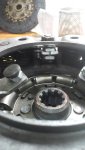
2016-09-14 12.22.54.jpg

2016-09-14 12.22.54 annotate _01.jpg

2016-09-14 12.13.00.jpg

2016-09-14 11.25.10.jpg

2016-09-14 11.24.58.jpg
 
Back
Top