Hi again. Did some more work…
no, I have not run the cam. I have not assembled the engine yet—taking one thing at a time when I can get a break from work and other things. It will be a while before I finally run it, since I also have to rebuild the tranny and eventually do a combo startup.
The cam lobes are not tapered, they are straight with faces parallel to the axis. I measured it two ways: squares, and with a .0005”grad indicator carriaged on my lathe.
I would be interested in any comments, suggestions, or any previous related experiences to this effort. Thanks in advance…
*the theory:
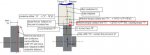
picture 01.. I decided to do what I could to modify the cam to get all lobes offset as needed. My diagram in picture 01... Shows my intent.
The “torque contact line” “tc” in my diagram has a torque arm radius measured to the lifter center. (recall your physics: contact force times friction coefficient equals sliding force.) the math all works out to use "tc", or the offset “o”, as a target value to look at for the ‘fix’. As the cam lobe gets narrower, the torque arm for a specific length “torque contact line” gets smaller. However the torque does not get smaller because the contact pressure per inch of total contact line across the lobe will get larger (same force, shorter line). Anyway…
*the setup:
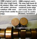
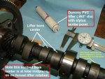
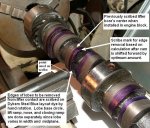
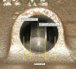
picture 02.. I made a dummy lifter out of pvc fittings with a scribe at the end (shown in photo) and put it through each lifter bore hole with the cam installed. I rotated the cam and marked the lobes with the lifter bore center all around as shown in picture 02… I then measured the width and distance from the edge of each lobe to its scribed line for all the lifters. The lobes for the right bank should be aft of the bore centerlines, and the lobes for the left bank should be forward of the bore centerlines.
I measured lobe width and corresponding local scribed lifter center offset (measuring distance to front/back face) at the lobes’ base circle, lift ramp, nose, and closing ramp for all 16 lobes.
The offsets should be of sufficient amount to rotate the lifters. Many are not (read on…).
*lobe widths and offset results:
as for the new cwc casting, it’s a bit disappointing, although only a little worse than my original cam. My new cam’s lobe widths differed by up to .050” measured at their base circles. In fact, lobe widths varied along each lobe, with the nose as much as .045” narrower than the tip. (btw: things must have changed or slipped: my original 1979 oem cam, also a cwc, had lobes that ran about .020” wider to .600”, and are not offset exactly the same.)
all of the lobes for the right bank were centered aft of their scribed lines, and all of the lobes on the left were forward—as they should be. But there is no cause for a hooray here.
While some were offset as much as .075” (giving me a .150” long contact line difference to rotate the lifter), all but one for the left bank had less than a .030” offset, and two lobes had less than .010” offset !!!!!
*a fix:
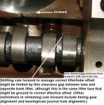
shifting the cam forward would improve the left bank offsets, but unfortunately it would be worse for a lobe for the right bank which had only a .035” offset. So, I made a spreadsheet and calculated what the best split would be between removing lobe edge material on all or most lobes and shifting the cam forward.
*limitations to the fix:
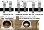
picture 03.. This photo shows there is a limit to moving the cam due to lobe-to-opposite bank lifter clearance. Note: the center distance between a right bank lifter and left bank lifter is 0.80”. A lifter is 0.995” diameter, so it should be obvious that in the photo the lobe on the left can only be offset forward, and the lobe on the right can only be offset aft. Particularly if the lobes were as wide as .600” (assuming the nubs on the lobe sides from the forging parting line are ground off). Other limits to camshaft being shifted forward are oil hole alignment between bearings and cam journals, and timing gear meshing.
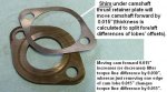
*the final fix:
picture 04.. I decided to shoot for a “torque contact line” as shown in red in my diagram in picture 01.. Of .095”, which is an offset of .048” for every lobe. By calculation in “splitting the difference” I came up with moving the camshaft 0.015” forward, note that moving it 0.015” increases the “torque contact line” length by .030” on the left bank’s lobes and increases offsets, but decreases offset on the right bank’s lobes by the same amount. See my 0.015” shim in picture 04.. That goes under the camshaft thrust retainer plate.
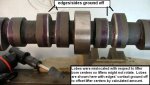
Picture 05.. I calculated the amount that would have to be removed from the side edge of each lobe to get my 0.095” “torque line” after the camshaft would be shimmed forward. This means some more lobes for the right bank would be ground than if I had not shimmed the cam forward, but it means less would be ground off the lobes for the left bank. The calculation was done for each part of each lobe (base, lift ramp, nose, close ramp). (some of the lobes were cast “wobbly”.)
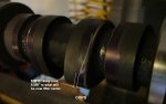
picture 06.. Here are the lobes with the edges ground away from contacting the lifter. I used an angle air grinder (shown) and a dremel tool to finish the edge smooth. Of course, if the lobes wear considerably, they negate the work. But if I get a successful break-in, I’m not going to worry about the next 150k miles.
*a screw-up:
picture 07.. Oops! (bumped my wrist finishing the very last lobe with the dremel.) and worse, its on the lifting ramp. While I am a bit of a perfectionist, I’m not sure I really want or need to do another cam. The .0015” depth was measured using my .0005” grad dial indicator moving the lathe carriage. Not enough for sliding friction oil support (no hydrodyamics here), but I think I’m going to try to live with it.
What do you think? Do another camshaft? (not)
*a typical result:
picture 08.. Lobe number 7 for the exhaust on cylinder #3 on the left bank had been the worst (less than .010” offset initially). Now it’s .046” offset (.092” “torque contact line” length in red in picture 01 diagram).
Comments? Suggestions? Any previous related experiences?
Thanks.
Ron