727 Rebuild help

NewcScout

Member
Hi guys!

So, up at the ihon festivities, I picked up the b+m transkit for my 727. It came with a direction book(very low res pics). I've read the munroe book. What else do I not know, or can't reference in those two books?

And I've waded through the 727 guapo too. But there's simply too much there to find what I need it seems.

This will be my first auto rebuild too.

Thanks for any help.

Cheers,
drew
 
Regarding the B&M parts kit, there is really nothing special in the box, just normal service parts used in any 727 rebuild.

The installation of the actual valve body modification components is a bit different compared to what I've previously posted for the trans-go kit. Some of the actual parts installation is done to the transmission case also so these items need to be addressed during the parts installation.

All components in this job must be surgically clean, including the inside of all hidden passages in the case. I do that in my shop by blasting it with the power washer.

The friction materials should be soaked for at least several hours in clean atf, same thing to be installed in the vehicle.

The governor assembly itself should be disassembled and cleaned also, then lubricated with a light oil (such as used in firearms cleaning) before being re-installed.

I have no doubt that you must use both references (I do constantly after 50+ years of doing this!!)...the B&M stuff is ok but as you have seen, it's printed resolution suks now. You must also positively id the transmission and it's design level as you pull it apart. There are many changes internally over the years.

Save the valve body service for last...it will be completely disassembled and all components washed in some sort of solvent.

I'd use this same thread and monitor your operation throughout posting pics as you go and also as you ask questions. I'll monitor the thread and make comments as needed.
 
Thanks michael. I appreciate the help, both now and upcoming.

A couple more questions before I start:

1. What is a good cleaner?(brand/type and how much I could expect to use)

2. Will standard parts cleaning brushes be adequate or do I need some special do-hickey brush?

3. Is hoppe's #9 ok for the governor lubricating?

4. Back to cleaning. Can you give me an idea what "surgical clean" practically means? (I.e. Cleaned with... Compressed air blown off... Placed in baggie...) how does this work in your shop?

Thanks again!!!!!
 
For spot cleaning anything around here that is not plastic or painted, I use the best carburetor cleaner I've ever found...that is the house brand stuff from walmart!! It's also by far the least expensive, local price currently is $1.87, two years ago it was selling for $0.97! I've never used a spray cleaner that is any more effective than this stuff and it's not been made stupid by environmental concerns. I use at least one and a half cans in a 727 rebuild for spot cleaning.

I have all kinds of cleaning brushes inside my actual solvent parts washer...but the plain old tapered brushes I snake from harbor freight work as well as anything else I've ever used.

The hoppes lube should work just fine. This lubrication is for the initial startup of the transmission. Once it's operating the actual working fluid operates the governor and lubricates.

In my shop, surgically clean means as clean as it can possibly be using normal shop processes. I use the carb cleaner when appropriate, the parts washer, compressed air, and the power washer as needed also. Items such as the governor are cleaned and then placed in a baggy until it's needed for assembly. My shop is also far cleaner than most any service garage, I do have a bunch of "stuff" scattered around but everything inside the building is very clean, and the inside gets blown out with an electric yard blower two or three times a day. No brooms around here!

By the way...yesterday I finally got into the 727 on my dd t-all that lost reverse while I was in texas. The low/reverse band broke which is the last item removed during an overhaul. So over the next few days I've got to pull the trans for a build.
 
Thanks michael

I'll go get myself a few cans of the wallyworld carb cleaner. And I already have a stash of new harbor freight tapered brushes. So I'm good there.

I appreciate the "normal shop processes" description.

I'll let you know how it progresses.:icon_biggrin:
 
Update #1

shop cleaned......
Parts assembled.....
Ready to go.....

I added in a before shot of the tranny before cleaning.
 

Attachments

  • 2011-01-06_20-48-40_904.jpg
    2011-01-06_20-48-40_904.jpg
    41.7 KB · Views: 649
  • 2011-07-04_20-36-46_517.jpg
    2011-07-04_20-36-46_517.jpg
    57.5 KB · Views: 458
  • 2011-07-04_20-38-09_824.jpg
    2011-07-04_20-38-09_824.jpg
    49.2 KB · Views: 484
Ok, so the disassembly begins. I don't know if anyone cares to see what I'm doing, but I'm posting anyhow. Perhaps it will be helpful to some. Down below when I refer to the manual, I mean the B&M manual.

And feel free to chime in as I've never done this before....

Before I started, here's my tranny pressure washed:
2011-07-04_20-38-09_824.jpg


First, pulled the pan:
dscf1319.jpg


Then pulled the valve body:
dscf1329.jpg


Here's a pic into the tranny after the valve body is removed:
dscf1333.jpg


It's worth saying now that there is a fair amount of what appears to be blackened atf in some of the pockets and passages. It's still the consistency of the atf, just black.

I then pulled the kickdown band adjuster and small piece of steel that holds the other side of the band(sorry for the lack of correct jargon). The band is now loose inside of the case:
dscf1338.jpg


Now onto pulling the pump. I used a chain to encourage the pump out. It didn't take much to get it to move out. I alternated from side to side, one link in either direction. The manual suggested using 2 slide hammers with the correct size bolts to pull it. I must be one of those weird people that only has one slide hammer.:icon_wink:
dscf1342.jpg


Here's the pump out of the case:
dscf1345.jpg


After that I pulled the input shaft along with the clutch packs. It just slides right out:
dscf1349.jpg


Oh, and here is what the little input shaft thrust washer bushing. The manual tells you not to lose it, but doesn't tell you what it looks like:
dscf1355.jpg


That's all for one night. More to come.........

Cheers,
drew
 
This will be a nice thread since obviously you have the workspace and tools to do this right! I've also used an engine stand for a service aid for many years but about a year ago I found/purchased a gurney as used in the hospital er and have turned it into a transmission workspace, all the tranny tools and supplies are now stored in the lower container.

Keep all washer/shims in their same locations as found during teardown. You will using the same items when you go back together unless there ends up being some clearance issue.

There are several design variations of some of the shims (and other parts) used over the years, but they all work just the same...evolution! Don't be concerned about many of your parts not matching the pics in either of your reference books! And as you have seen there are several variations of the valve body. When doing it, you must be very careful about how your valve body is assembled and keep the parts as found, replacing or eliminating only those parts used in the B&M kit.

Filter looks real clean, this transmission must not have failed previously? The black gunk is the real issue inside the valve body, that is the stuff that will create valve stick or hangup after it's put back together and must be totally eliminated during the rebuild process.
 
Great post, drew. I have only looked over someone's shoulder r&ring an auto trans. Love the pics. How did you post them directly into your text?
Keep it coming. Its a great learning tool for the rest of us.
 
The po told me that this tranny didn't go into reverse even after the band adjustment. My thoughts were that while it was out, I might as well have some fun with it. And to me fun = rebuild.

So I don't know if it had ever been worked on before.

Dealbreaker
if you set up a photobucket account, you can copy the pics from the photobucket website and use the "insert image" button in the post toolbar to copy the link directly in.
 
Ok. I have got it down to the bare case. A couple of quick questions.

1. I can't seem to find any directions on what to do with the output shaft housing. For instance, how to disassemble.

2. I've read a couple of things about deburring inside your case. I'm going to drop the case off at the tranny shop tomorrow for a cleaning and wanted to deburr before I get it cleaned. Does this seem like a worthwhile thing to do?

I'll be posting pics and steps in a bit. Stay tuned....

Cheers,
 
Alright, here we go. Round 2.

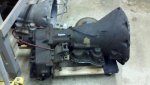
So here's where I left it. Disassembled to the overrunning clutch assembly.
dscf1372.jpg


So then I pulled the overrunning clutch inside race. It took a little tug with the needlenose pliers. And, yes my heart sank as all of the rollers and springs rattled down and fell out.
dscf1374.jpg

Here are the the springs and rollers:
dscf1376.jpg


Getting the low-reverse band off seemed a little clunky, but it came off just like the instructions said. I had to tilt the tranny up on it's output gear to lift up on the rear servo lever. Here is the band and the strut.
dscf1382.jpg


Next, 6 bolts for the output shaft extension removal. Came right off.
dscf1386.jpg


Then the output shaft support, 4 more bolts. Again, came right out.
dscf1393.jpg


The front servo kickdown assembly was next. This was a bit of a pain. The directions said to simply "hold your thumb over it to keep it from flying out when the retaining ring is removed. It seemed like I could damage the retaining clip groove if I didn't apply pressure to the servo cover. It really didn't take much, but I couldn't do it with my thumb, so I used a big c-clamp and a socket so as not to push directly on the rod. But it all came out. There was a huge amount of sludgy black stuff up under the servo cover. With everything else so clean it was odd to see this so nasty.
Here are the pieces once removed.
dscf1401.jpg


The accumulator piston pulled straight our with my hand.
dscf1402.jpg


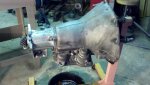
Removal of the reverse band lever shaft seemed to work best at this angle.
dscf1408.jpg


Here is that assembly once out of the case. I slid the shaft back through the pieces just to keep them all straight.
dscf1412.jpg


Same issue with putting a little pressure on the low/reverse servo. Bit it all came out ok too.
dscf1415.jpg


Removing the front kickdown shaft and lever. This part wasn't in the directions at all. There is a small plug inside the bell housing above the front pump. It takes a 1/4" square socket drive to remove.
dscf1421.jpg


You'll need to walk it out with a pair of needle nose pliers as there is no way to get at the back side of the shaft. Once out it will look like this.
dscf1425.jpg


Remove the neutral safety switch.
dscf1419.jpg


No pictures for this, but I removed the 3 1/8" pipe plugs and the cooler line fittings as well.

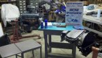
Voila! One bare case. Off to the shop to get cleaned.

Until next time.......:ihih:
 
Here's the bare case by the way. This forum software limits you to 15 pictures per post. So here's the 16th of the bunch.
dscf1429.jpg
 
Ok. So I dropped off the case and output shaft housing at the tranny shop for cleaning. Hopefully they come back real pretty.

Anyhow, here's what I did last night.....

I removed this piece. This looks like it is possibly the place where the speedometer would normally have it's gear. But since the speedo cable on our scouts comes off of the t-case, this looks as though it's only a cover and doesn't do anything with the spiral gearing on the output shaft that you can see when you pull this off.
dscf1432.jpg


Took off the output gear with an impact wrench. 1 1/4 socket.
dscf1435.jpg


The complete output shaft assembly slides right out.
dscf1436.jpg


Output shaft seal bushing then can be pulled right out with your fingers.
dscf1438.jpg


Now onto the output bearing. The retaining ring down in the housing is a pain to get out. It takes a little gentle working due to the fact that everything is aluminum.
dscf1441.jpg


Next I pulled the little parking break shaft deflector doohickey. You need to remove the clip and gently pry it upwards out of the housing.
dscf1443.jpg


Now you can pull the parking break arm shaft out using one side of a pair of needle nose pliers and putting it in the hole in the end of the shaft and applying sideways pressure. It will just slide out.
dscf1444.jpg


I removed this little plug that looks like it May be the drain for the output housing.
dscf1446.jpg


Push out the shaft seal and I'm done!
dscf1445.jpg


I dropped off the case and output shaft housing at the tranny shop this morning and will get them this afternoon.

I'll post some pics of the freshened units later....


Cheers,
 
ok. I have got it down to the bare case. A couple of quick questions.

1. I can't seem to find any directions on what to do with the output shaft housing. For instance, how to disassemble.

2. I've read a couple of things about deburring inside your case. I'm going to drop the case off at the tranny shop tomorrow for a cleaning and wanted to deburr before I get it cleaned. Does this seem like a worthwhile thing to do?

I'll be posting pics and steps in a bit. Stay tuned....

Cheers,

Deburring a transmission case probably does have an advantage when performed on a transmission that is going to see 600+ horsepower. But is totally meaningless on a unit used in these vehicles. I'd never take the time to do that myself.

I have seen exactly one 727 with a case that was broken with the transmission in use. And that is a unit that we worked with on Matt g.'s sii about two months ago. The unit is here on the shop floor and has a very strange breakout in the low/reverse piston bore hole to the outside of the case. But that was caused by breakage of the band application anchor, which in turn broke out the case. That had nothing to do with a potential for case cracking due to stress in the casting.
 
Many of the actual service operations you have done are not actually performed in a shop during a rebuild. The detail depends upon what parts are actually damaged, and whether or not some sort of shift improvement system is going to be installed.

The plug for the speedo drive is just that...a plug made up of parts of the drive system with a blanker cap installed. Nothing here is out of the ordinary for a "married" transmission assembly. The tick marks are used when the actual drive gears are replaced so that the speedo will match the drive axle gears in the typical 2x4 vehicle installation and have no meaning at all on this system.

To remove (and install) the transfer case adapter housing bearing, I normally heat the housing in the oven at 300* for about thirty minutes, the bearing will fall right out. That bearing is a "special" and has not been available new in many years. So we have those made for us by precision bearing, those are carried in our online store.

The 1/8" npt plug in the bottom of the housing is an access port for governor pressure, same as all the other plugs found in the case. These are used with a set of pressure gauges for service diagnosis in some cases. But transmission pressure tests are not something I normally do since we don't normally rebuild 'em until they don't work!

None of the details for handling the tailhousing on these married transmissions is discussed in your references, that info is found in the appropriate IH service manual though.
 
Thanks for more insight michael. Here's the latest.

I got back the case and the output shaft housing from the tranny shop. Nice and pretty. Looks like it runs great:ihih:

dscf1450.jpg


Onto more important things...
I'm now into dissasembling the specific subassemblies of the 727. I started with the pump. Here it is pulled apart. This really just falls apart after you take the 6 bolts out. Careful there as you will need a thin-walled socket to get a couple of the bolts out.

dscf1454.jpg


Next I dove into the front clutch assembly. Pull the front snap ring and pulled the plates.
dscf1457.jpg

dscf1460.jpg


Then I used 2 c-clamps to depress the return spring retainer. The retainer steel is somewhat soft and I could potentially see this being deformed by applying too much force. I tried to position the clamps directly over the springs and only push far enough for the clip retaining flanges on the retainer to get out of the way of the clip.

dscf1462.jpg


After pulling out the retainer and the 9 springs(there were studs for 15) I pulled the clutch and saw the first real wear point inside the tranny on the outer rubber seal.

dscf1467.jpg

dscf1471.jpg


2 more snap rings and the rear clutch is apart too.

dscf1477.jpg

dscf1478.jpg


The rear clutch drum just slides off now.

dscf1479.jpg


Now onto taking apart the governor. I pulled the little c-clip and pulled the shaft out. Then I pulled the clip on the other side of the governor.

dscf1483.jpg

dscf1484.jpg


Disassembly complete.....
 
After I had it all apart, the B&M instructions say that you should jump right into taking apart the valve body.

My thought is that I now have pieces laying out in boxes and under rags all over the shop and I wanted to put some of this thing back together before I forget how it all came apart.:icon_wink:

so I started with the pump....
I carefully inspected everywhere that the instructions said I should. There doesn't seem to be any buildup/sludge/dirt/junk/gunk anywhere in this tranny. It is as if I didn't really need to clean out the pump at all. But I did. Then pre-lubed everything with atf.
The B&M instructions say to drill out the hole in the reaction shaft up to 9/64. This is a pretty large increase in this hole. The stock hole measures about 3/64.
There isn't much material to go through and it's pretty easy to do on the drill press.
dscf1486.jpg


I then put on new seal rings and input shaft seal.
dscf1488.jpg

dscf1489.jpg


**question from here**
the instructions say to place the pump down onto the torque converter and spin the pump to make sure all things are moving ok. It says that it should spin freely with a little resistance. Well, when I do this the pump falls all the way down until the case of the pump rests on the torque converter. Spinning it only causes the pump housing to rub on the torque converter. You need to lift it up off the converter slightly in order for it not to grind. But at that point, how can you tell if it's spinning freely? It's not light and it will fall right back down if I let go. Is this a lame test on the part of B&M or am I doing some thing wrong?

The next reassembly step is the rear clutch. The clutches are soaking overnight by the way.... But, the instructions also call for the expansion of the holes in the rear clutch piston retainer. It wants the 3/32 holes drilled out to 5/32 holes. And to add more if you don't have 18 holes already. And then, at the innermost holes, angle them by 70-75 degrees.
Here's my question there: the drawing in the book isn't really clear. Is it really 5/32? I can't tell if that's a 5 or not.


Thanks for all the help!!!!
 
The correct hole re-size is 5/32" in the rear drum retainer.

Don't sweat the oil pump configuration, all you are doing is removing, cleaning, measuring, and doing the reassembly. No parts replacement. The torque converter will establish the drive clearance on the pump rotor once it's bolted to the flex plate.

Keep in mind all these suggested changes are done for all units produced over a 25 year production span, many units already have most of those mods made.

Everything gets lubed with transemble during parts re-installation. Be sure to not assemble any of the metallic rings in a position where their endgaps line up, they must be offset.

I always do the valve body service after the entire unit is reassembled. Some parts are of course installed in the transmission case during the build, but the valve body is always handled separately.
 
Back
Top