350 Buck Truck Project engine revival

I took measurements that are easier to get especialy on the angled exhaust valve.

Exhaust:
stem tip : top of stem to top of rotator. 2.300
spring installed length: 1.850 to top of .050 washer

intake:
stem tip : top of stem to top of head surface. 2.150
spring installed length: 1.850 to top of .050 washer.

In a perfect world these should all be +/- .020 but +.040 and -
.025 the lifter should still be well with in its range.
 
I don't think I have mastered the art of pumping up lifters by hand yet. Both of these are right out of the box but I could not pump them up on the bench 2 days ago in 5w20 oil. The first one is in mineral spirits (kinda like kerosene the manual mentions). The second one is in 5w20. Is there anything wrong here or is this normal?


I grabbed another one out of the box and it farted a steady stream of bubbles on the first stroke. Second stroke it bubbled again and began to firm up. By then end of 4 strokes it had pumped up.

I posted this in basic tech too in case someone is not following this thread but has some answers.

Edit: I still don't know if these lifters are good. I am spending a little time with them on the bench because it is a diversion until I get the energy to get up on that block and pull the rocker shafts to check installed valve height against roberts #s. Also I need to have a sit down with the machine shop and grill these guys again as to their valve work methods related to the nature if IH non adjustable drive trains even though they assured me already they were savvy. One loophole is I don't know if the po did anything to alter the geometry of the valve train like shave the heads. I am going to chase this thing down even if it means tearing the motor down again. To verify that these lifters are good I will send a sample today to Robert k see what he can determine. Maybe you can't fill these lifters on the bench by soaking and stroking unless there is vacuum present or oil pressure. The only thing I know at this point is that the lifters that primed easily on the bench required almost no effort. Just a few slow, firm strokes and they were solid.
 
Last edited:
You are doing a great job working through all of these problems and don't want to take away from your conclusions but I just want to add a quick note for the time being.

One thing to remember about the environment in which the lifter lives. First and foremost the annular oil undercut is supplied with some amount of pressure. The pressure will have the effect of motivating the oil in to the lifter body and the air out. Just sitting in the container of liquid May not be enough to accomplish that. Yes some did pump up but the other say 6-7 did not.

This situation is not conclusive as never has an individual that I know has ever had 6 of 8 new lifters fail to pump up in an engine. Remember I have never pre-pumped up lifters in my life only dip them in engine oil and never had one fail to pump up. I have had bad wear characteristics but never a flat one.

My fear is that the readers will conclude this as a valid test that shows johnson or any other lifter is bad and that they should be avoided.

That is why I want to see one or even one of the new ones you are having trouble with. If they look and function then I would bet on another issue. But I won't jump to any conclusions till then
 
Robert's right. No way multiple new lifters are bad.
Robert, what do you feel is a comfortable pre-load measurement on a hydraulic lifter in this (mostly stock) situation? I've always went about .030-.070", though I have never seen any number published in the manual.
 
I finally found a technique for pumping up lifters on the bench that won't pump up easily in a cup of oil. I found that laying them on their sides for a soak in mineral spirits that they would begin to release bubbles on their own. Then I would shake them one at a time and soak them again on their sides and more bubbles began to come out. I repeated these steps a few times. Then I would very slowly apply even pressure with a pushrod and hold. Some of them would release a nice steady stream of bubbles after just a few slowww plunges. Some took a little longer and I just repeated the earlier steps a few more times. All lifters on the bench that I thought would not pump up did. There was a small amount of metallic colored dust left in the bottom of the cottage cheese container I was using to submerge the lifters in mineral spirits by the time I was done.

Each of these so called "problem" lifters took about 10 minutes of gentle massaging to begin to pump up by hand.
 
What do you feel is a comfortable pre-load measurement on a hydraulic lifter in this (mostly stock) situation? I've always went about .030-.070", though I have never seen any number published in the manual.

Probably a good range .050 being nominal. I would stay at the higher end closer to .050-.070 so you could absorb more wear.

I consider .030 an absolute minimum.

Recommended lifter preload for a typical GM lifter is 3/4 - 1 turn down on a 3/8-20 stud = .050 at the fulcrum and .083 at the lifter end assuming the rockerarm is rotating around the valve and while the fulcrum is moved down .050.

All lifters used in similar vintage push rod applications from a design and function standpoint are a like. An IH spec lifter has like usable range so one can conclude both will function properly with similar preload.
 
probably a good range .050 being nominal. I would stay at the higher end closer to .050-.070 so you could absorb more wear.

I consider .030 an absolute minimum.

Recommended lifter preload for a typical GM lifter is 3/4 - 1 turn down on a 3/8-20 stud = .050 at the fulcrum and .083 at the lifter end assuming the rockerarm is rotating around the valve and while the fulcrum is moved down .050.

All lifters used in similar vintage push rod applications from a design and function standpoint are a like. An IH spec lifter has like usable range so one can conclude both will function properly with similar preload.

Copy that. Thanks.
 
6cd3beef.jpg


#4 int preload measured like dealbreaker74
 
Good idea. Use the resources at hand so kiss rules again.

.070 is spot on in my book. If all are similar look else where for root cause.
 
Okay, now you're getting some solid info. Did they all land somewhere close to this? If yes, then like Robert says, check pushrods off your list and move on to something else.
Keep in touch. We really want to know what's really causing this drama!
 
0758a096.jpg


#2 intake lifter preload

fd3a84b4.jpg


#2 exh preload

this quick method May not be 100% accurate it is within specs

while I had # 4 int lifter out I cranked and cranked and saw no oil flow out of lifter bore

to recap the noisiest collapsed lifters 4 int and 2 exh were replaced with primed lifters. On startup lite clacking went away, normal exh sounds 5 mins the collapsed lifters. Repeat performance with 4 int and 2 exh replaced with originals hand primed. Must be something wrong in 2468 lifter gallery.

304 coming back out
 
Also at the end of day yesterday changed filter to napa gold and 15w40 diesel oil. Oil pressure was roughly same with breakin oil on shop gauge . Dropped to 19 lbs hot was 50 cold at high idle. Hot high idle 45. Shop gauge installed in stock sending unit hole
 
Zero change with new oil/filter after a 20 minute runtime. 1357 no issues from get go. Funny that was bank with flat cam lobes when I got truck . Originally no problems with 2468. And heads were reinstalled in original locations.
 
The oil supply to the lifters comes by way of the last cam bearing. It migrates around the block cover. If the cam bearing protrudes too far aft, or the proper gasket wasn't used under the plate, then there could be a diminished volume of oil to the lifter galleys. Not sure how one would be affected more than another though.
You are sure the even side (passenger) is providing less oil than the drivers side?

Edit:
I can't remember how the front of the lifter galley gets plugged. Is it the timing cover? I don't remember any pipe plugs. Am I on drugs? Diminished oil volume could mean an internal bleed in that particular galley.
 
Last edited:
I've been in frequent communication with steve on this problem.

I have carefully examined the oil system diagram in the IH truck service manual. Each bank of cam tappets are supplied with oil from a gallery that comes from the rear cam bearing area. Pressurized oil that leaks from the rear side of the cam journal fills the cavity area created by the rear cover plate for the cam. Oil then flows forward, through a hole in the block on either side of the cam bearing saddle area, to the left and right tappet galleries. The manual notes that the oil supplied to the tappets is intermittent, and at a reduced pressure. There is a plug for each gallery at the front of the block.

I'm pretty sure I would have noticed a missing plug at the front of the block when the short block was on the engine stand. A leak from the cam rear cover plate should be very noticeable down the back of the block. There is a slim chance that the front plug is not fully sealing (seeping through the threads).

My line of thinking now shifts to a possible clogged oil gallery for the right tappet bank.
 
Here are the supply/lifter gallery specifics and pictures. Picture of the front is pretty clear.. A small leak from the threads won't cause a problem in pressure.

The rear cam journal has an annular groove in it that is fed by the cross drilled hole that also feeds the rear main through a hole in the rear cam bearing at the 6:00 position.
The rear cam journal is cross drilled 3/16 diameter all the was across. It intersects the annular groove. The cross drilled hole also intersects 1 3/8 hole drilled perpendicular to and centered on the rear face of the cam. The 3/8 hole supplys oil to the chamber behind the cam that feeds the lifter galleries.

The lifter galleries are about 1/2" in diameter so no way those get blocked. The other passages are shared by both lg's but are smaller. The cam rotation cam cause oil flow to favor one lg if flow is limited.
 

Attachments

  • 392fvNONICMU.JPG
    392fvNONICMU.JPG
    84.8 KB · Views: 689
Good explanation Robert. I can't access my pics right now and was going by memory. I agree oil "seeping" past a pipe plug is not what we are talking about. A missing plug is more likely causing such a loss. I once forgot the big welch plug under the timing cover (main oil galley). Priming it only produced 5 psi. Glad I didn't start it!
Could anything else be missing or blocking that galley?
 
...a small leak from the threads won't cause a problem in pressure...

The rear cam journal has an annular groove in it... ...the rear cam journal is cross drilled 3/16 diameter all the was across...

The lifter galleries are about 1/2" in diameter so no way those get blocked...

That's why I said *slim chance* on the plug leakage: not probable.

I wouldn't say *no way* for a tappet oil gallery to get plugged. Maybe not very likely, but could be possible.

Interesting thought on the oil passage drilling and groove in the camshaft. I don't recall inspecting the camshaft before it was installed.

From what steve has described so far, it seems like the right side lifters are not receiving enough oil pressure.
 
I have some good pix of the rear journal for referance.

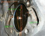
Thinking now about it the symptomes steve told me, I wonder if the right side plug is missing. Kinda hidden under the dizzy hole.

Seems to quiet down upon initial cold start but after the oil gets hot the lifters go flat. Btw I left it out on my 152 when I built it 6 years ago.:icon_gonk: so the thought doesn't suprise me. :icon_rolleyes:
 
Last edited:
Roger that! I will pull the dizzy and break out the dental mirror in the next short while. Now where is that 1/4 drive sidewinder?
 
roger that! I will pull the dizzy and break out the dental mirror in the next short while. Now where is that 1/4 drive sidewinder?

Man----- steve if it is missing and if you can get it in you are a master contortionist, I must have spent 4 hours screwing around and finally gave up and pulled the front cover. I could see it and get a tool close but just couldn't do it. :idea:

but if it can be done you will find a way.

Crude lifter gallery oil flow diagram.

10782d1282176713-350-buck-truck-project-engine-revival-oiling-flow-diag.jpg


10784d1282178152-350-buck-truck-project-engine-revival-cam-groove-mu.jpg
 

Attachments

  • OILING FLOW DIAG.jpg
    OILING FLOW DIAG.jpg
    77.3 KB · Views: 623
  • CAM GROOVE MU.jpg
    CAM GROOVE MU.jpg
    29.7 KB · Views: 614
Last edited:
Pictures are worth a thousand words.
You could possibly pull the timing cover and rotate it enough to get a view of the plug locations without actually pulling the balancer off. When I figured out I had left out that main galley welch plug, I yarded out the radiator, water pump and eventually the balancer too because I boogered up the timing cover gasket too bad to re-use it. But I didn't have to pull the motor.
 
Well steve, I don't know whether to cheer or say sorry man.

At least you have the answer. :icon_wink:

1/4" npt plug. Needs to be flush internal wrenching like the square drive stockers to leave room for the distributer drive gear. I buy allen drive plugs by the box so I don't run out.
 
Back
Top