

First off I am new to the International/Scout world so take it easy on me.
I bought a 1974 Scout II with the 345 and 3 speed automatic a while back. When I got the truck it was smoking like a freight train so I knew it had to be rebuilt. When checking around for a rebuild kit, a very competent machine shop had a complete engine that was already built. The story on the motor was he built it 4 years previous for a guy that never picked it up and he wanted to get rid of it. He said he went completely through the motor and put all new valvetrain parts, 3 connecting rods, new pistons and turned the crank 10/10. This engine came out of a heavy duty truck with a standard shift behind it. It also included the original balancer that came on the engine with it.
So I installed the engine and the first thing I thought was that the engine was going to shake itself apart. So the set up I had was the original engine balancer and my flexplate from the Scout for the automatic transmission. So a call back to the machine shop and he advised to change the balancer to the one that came on the Scout. So this is what I did and it made absolutely no difference. At this point the machine shop was out of answers.
Does anyone know how International balanced these motors? Was the crank "0" balance and the external parts balanced to each other or was the crank, balancer and flexplate all balanced as a unit?
I have definitely run out of options and really want to keep the original motor but these vibrations have me stumped.

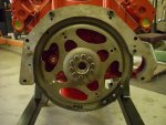
 you have the tf727 trans you will have a spacer that the goes between the crank and the flex plate. You need to index the roll pin to the correct through hole.