Servicing a T-28 Transmission / Borg Warner Model 8 Transmission

Beluga

Member
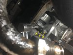
This thread is documenting my fluid replacement and band adjustment for my Travelall. Because I have an older transmission, there isn't much information on it from an IH standpoint. If you have a 727 transmission, you'll be overloaded with threads, but little is available on this model, especially for a newbie just trying to do basic servicing. So here it is.

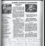
As many have posted previously, the borg warner transmissions were used by many different manufacturers on many different applications. I found most of what I needed off of Ford and studebaker forums.

IH designated this model 13028 on the line setting or t-28 transmission. Searching that gave me nothing, but searching bw model 8 is how I found quite a bit more from amc / Ford / studebaker forums.

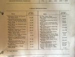
I happen to have the IH manual and cts 2281 covers this specific transmission. But, it doesn't go into enough detail for someone who has never changed their atf fluid or serviced the bands.

I am a novice. Many on this forum may find this too simplistic, but I am just trying to help out the next guy. If you have any tips to add, please do! Thanks.

I have also reinserted all the pics 4+ years after originally posting this. I hope they are in order!

IMG_2528.jpg


IMG_2541.jpg
IMG_2542.jpg
IMG_2543.jpg
 

Attachments

  • IMG_2610.jpg
    IMG_2610.jpg
    167.5 KB · Views: 311
Last edited:
This is the converter housing front plate (green arrow).
It only covers the lower 1/2 of the bell housing.
There are 4 bolts to remove with lock washers.
Bolts are 9/16" and 2 of them have spacers.
The 2 with spacers hold a separate "deflector plate" indicated by the red arrow. I am not sure why there is a deflector plate unless it is to deflect the heat from the exhaust pipe just to the side of it. But there is no mention of this plate in the manual.
**edit - that "deflector plate" actually covers an opening in the bell housing. Why is there an opening? For cooling?**

btw - at the end of cts 2281, and most chapters in the IH manual, they will have the torque specs for the majority of the bolts mentioned within that chapter.
InkedIMG_2529_LI.jpg
 
Last edited:
You might take pics before removal so you know how it goes back together, but once you have the converter plate off, set it aside and clean it.
Keep your bolts and spacers organized.

This is what you will see.

IMG_2534.jpg

What surprises me it that there was no gasket between the cover plate and the inside.

The toothed disc is the ring gear.

The converter housing plate has two holes in it, the holes are 180 degrees from each other. Within each hole is a bolt and these are the converter drain plugs. They are also 3/8".
These are indicated by the green arrow.

InkedIMG_2533_LI.jpg

Get your fluid/oil collecting pan ready, cuz when you pull that plug, about 6 quarts of fluid will drain out. Do not drop that bolt into the converter housing plate. I don't have any idea where that would go and don't want to find out.

IMG_2536.jpg

There the fluid drains for about 20 minutes.
Then you rotate the ring gear 180 degrees to access the second bolt, which looks identical to the first, and you do the same thing.
To rotate, I used a big flat scredriver on the teeth and pushed hard. The truck was in park, e-brake on, and chocked. The ring gear moved without a problem, just took some force.
Btw - I got zero fluid from the second bolt. Maybe it all came out from the first drain plug.
Remember to torque those bolts back in properly. Manual says 7-10 foot/pounds.
 
Last edited:
Next comes disconnecting the fluid filler tube. This is where your transmission fluid dipstick goes and the same place you fill the atf from.

Make sure you disconnect this before the pan bolts are loosened.

It took an an adjustable wrench and some leg torque to loosen that connection. You can see in the pic (green arrows) how it was connected.

InkedIMG_2530_LI.jpg

Another 4 or so quarts will drain immediately.

The red circle is a heads-up. The fluid, as it poured out, got all over the exhaust pipe. As you can imagine, once I start the truck, this will heat up and burn and I imagine it will smell like hell. So remember to clean this off when you're done.

InkedIMG_2538_LI.jpg
 
Last edited:
After the fluid stops draining, then remove the 14 bolts of the transmission pan. There is a cork gasket that May keep it sticking to the tranny, but just pry the pan off. You'll need a new gasket anyway and it's available from most autoparts shops. Just remember it's the 14-bolt pattern and looks like this (pic from o'reilly's computer).

IMG_2527.JPG


Here's the pan off. The fluid looks and smells good. The greyish slush is normal and comes from the wear of the belts.

InkedIMG_2539_LI.jpg


The red circle is just to bring your attention to the bolt holes. If the bolts have been over-tightened in the past, then the holes May not be flat and the edges will stand proud. You'll need to hammer them back flat so that the gasket lays flat and it's less likely the pan will leak.
 
Last edited:
Here's the pan cleaned up and the new gasket ready for reinstall.

IMG_2599.jpg

But before that, the screen (red arrow) needs to be removed and cleaned. As you can see in the pics, there is a metal strap (blue arrow) that you remove to get the screen off. The screen itself will also hold fluid, so be prepared for that. There is no other filter that needs to be serviced in this transmission type.

InkedIMG_2584_LI.jpg


Amazingly, my screen was super clean. I don't know if it's original or an aftermarket. When you reinstall it, make sure you get the metal tubes going back into the screen where the holes are. It's self-explanatory when you see it.

IMG_2540.jpg
IMG_2585.jpg
IMG_2586.jpg
 
Last edited:
Before you put the screen back on or the pan, there are two band adjustments that need to be made.
In truth, you do the front band adjustment with the pan off. But the rear band adjustment is done on the outside of the tranny and can be done with everything already buttoned up.

The manual outlines the procedure pretty well. But I also checked the other makes (Ford, studebaker, amc, etc) to see if their's differed.. And there was some difference. For example, these Ford instructions are exactly the same, except for backing off one turn on the front band adjustment.

http://www.fatsco.net/assets/cast-iron-Ford.pdf

Ford-o-matic, flight-o-matic, cruise-o-matic, fmx, merc-o-matic, etc. These were all berg-warners and virtually identical. But there were differences in how you did the adjustment. Which was both confusing and helpful.

The IH instructions are super easy if You have the specific tools se-1909 and se-1910. Essentially these are torque wrenches set at one specific setting and instead of a socket at the working end, it's probably a flat head screwdriver-like tool. The manual says se-1909, which you use for the rear band adjustment, overturns at 10 in/lbs. The manual never says what at what torque setting is for the se-1910 tool used for the front band adjustment. This is where looking at all the other borg-warner makes and models helps somewhat. I came away with that se-1910 is also set to overturn at 10 lb/inches, but I cannot find that documented in any IH literature anywhere.

So before I get to how I did the band adjustment, I have two questions for those folks with experience with these transmissions.

Again, its a t-28 or borg-warner model 8.

1. Do you think that the front belt adjustment bolt is torqued to 10 in/lbs?
2. Every other resource that was not IH backs off that bolt after getting it torqued. The IH manual does not back off the bolt at all. It gets tightened down right at that setting. Do you think this is accurate?

Any input is appreciated!
 
Nice job with the write-up. This thread should be sticky-ed so it stays near the top and doesn't get buried by new threads. I might have the technology to make that happen. I have some experience with the tf 727, but not the bw models. Looking in my sii manual which includes a section for the t-39, t-49 and t-409, which are just later version of what you have. Those instructions are similar to what you've noted with respect to the front band being torqued with special tool se 2273, but not backed off, while the rear band is torqued with se 2248 and then backed off exactly one and a quarter turns.
 
Thanks scoutboy, I looked at those sections also and found exactly what you found.
I wonder if anyone even has those tools anymore.
I certainly don't, so here's what I did.

Front band adjustment

Here's the front band adjusting area of interest

IMG_2583.jpg


InkedIMG_2596_LI.jpg


This is where the magic happens.
X is the adjusting screw.
Y is the locknut.
Z is the actuating rod.

First loosen the locknut "2 full turns" and back off the actuating rod a bit, just to really make sure it moves freely.
In reference to the picture, you then pull the actuating rod to the left and it opens a gap between the end of the adjusting screw and the servo piston stem on the right. Then you insert a 1/4" metal block into the gap you created and let go of the actuating rod. The squeeze from the rod will hold it in place. Tighten down the adjusting screw to, what we are assuming is 10 inch/lbs, and then re-tighten the locknut.
All those instructions are in the manual and the pages I posted in the first post.
But since no one I know of has the special se-1910 tool with the attached block, I had to improvise.

Here's the "metal block" I made from a spark plug feeler gauge. This allowed me to use a measuring caliper to get at close to 1/4" as possible. Then I taped them together so they wouldn't slip. I suppose you could add up all the feelers thickness individually to get 1/4", but that's too tedious.

IMG_2600.jpg


Hey, it's ghetto, but it worked. Plus, use the feelers that are thicker. If you use the thin ones, they might dent when you are torquing down the adjusting nut.
 

Attachments

  • InkedIMG_2596_LI.jpg
    InkedIMG_2596_LI.jpg
    98.5 KB · Views: 220
Last edited:
For the se-1910 tool I used a inch/lbs torque wrench from o'reilly's, though most auto parts shops have them.
Then I added on a various bits from my socket set and screwdriver bits to make se-1910 2.0!

IMG_2587.jpg


IMG_2588.jpg

The feeler gauge is pinned between the adjusting screw and the servo piston stem (which by the way, looks like a 1/4" metal nipple).
The torque wrench fit pretty well and I was able to move it through about a 90 degree arc. This amount of throw was good enough to get a decent feel for when I reached 10 inch/pounds.

Remember, after that, you simple use a normal foot/lbs torque wrench to tighten back down the locknut to 20-25 ft/lbs.
As you tighten the locknut, the adjusting screw should not turn with it, or obviously it would itself torque above the 10 inch/lbs. Since you can't see the adjusting screw while torquing the locknut, you have to memorize the position of the screwdriver slot and make sure it stays.

Then you pull out the "metal block" and you're done.
You can put the pan and new gasket back on . Don't over-torque the pan nuts. You can also attach the dipstick tube. I left the dipstick tube off, because it made it easier to get at the rear band adjusting nut, but this isn't mandatory.
 
Last edited:
Rear band adjustment

InkedIMG_2530_LI2.jpg

There it is on the passenger side of the tranny. Even if you could get the torque wrench up there, it's not a clicker type, so how can you see the gauge when you reach 10 inch/lbs?

Well the nut points up to the passenger floor, right at this little port...

IMG_2532.jpg

Pull your carpet back on the passenger side and you'll find it..

IMG_2597.jpg

How cool is that?!?! So you pop that off with a flathead screwdriver and peek into the hole. You'll see this..

IMG_2602.jpg

This makes the adjustment much easier and could be done with one person, but two does make it quicker.
 
Last edited:
So the adjustment..
It's pretty straightforward, there is no metal block.
You just loosen the locknut, torque the adjustment bolt, back it off 1 and 1/2 turns, then torque the locknut back down.

There's two main differences. First is that the adjustment "thingy" is not a screw, it's a square bolt. So you do not want to round that off by using a 6-point or 12-point socket. You must use an 8-point socket.
Those are also sold at autoparts stores and at sears. Cheaper at the autoparts stores.

Second difference is you're going to back off the adjustment bolt after torquing it.

Here's the socket and it's 5/16".

IMG_2609.jpg

You'll need a long extension

IMG_2608.jpg

So I stayed up in the cab and torqued the adjusting bolt to 10 inch/pounds (remember, you back this bolt off 1.5 turns after torquing it) while my son used a open-ended wrench to loosen, then tighten, the locknut. He did that from below.

Then like the other adjustment, I rechecked the torque of the locknut (35-40 foot/pounds) making sure the adjustment bolt hadn't moved.

IMG_2598.jpg

Follow the procedure for refilling the atf and checking the level.

Here's the torque specs for cts-2281 that's at the end of the chapter. Note the asterisk that denotes when the specs are in foot/pounds or inch/pounds. That's kinda important.

IMG_2610.jpg

Hope this helps somebody. I will edit any corrections that need to be made, just let me know. Especially if anyone has different knowledge about the torque of that front adjustment screw.
Craig
 

Attachments

  • T28AutomaticTransmissionBandAdjustment.jpg
    T28AutomaticTransmissionBandAdjustment.jpg
    89.8 KB · Views: 1,319
Last edited:
This is an excellent write-up. I read this just for grins, but then realized that I once owned a 1972 volvo with a big straight six in it, and it had the bw35 tranny. Adjusting that rear band brought back a memory. As on your truck, you gained access to the fitting through a plugged hole in the floor pan. I once had the special extension wrench that volvo specified for the job, but as you discovered, you can improvise quite nicely.

I wonder why IH didn't put an access hole w/plug on the Scout II tunnel to pull the t/c lever "pin". Would make pulling a transfer case a lot easier. Now reaching for a 1" hole saw....
 
According to the STS, Automatic Transmission Fluid "Type A".
Having no idea what that alluded to back in 1966, I used Valvoline Max Life ATF.
 
This is the BEST write up I've seen on these old BW's from a service standpoint!! Methodical, researched, and well done going on the manual for reference. I like these old gals, they go the distance with just an occasional TLC.

Type A and B transmission fluids where the fore runners of Dexron. You could have put good old Dexron in there and been just fine.
 
According to the STS, Automatic Transmission Fluid "Type A".
Having no idea what that alluded to back in 1966, I used Valvoline Max Life ATF.

Thanks for the information. I was in the process of changing the fluid when I found your write up. Very informative. I put the Valvoline Max Life in upon your recommendation. I also put a can of Trans-X with it. The transmission is shifting beautifully again, as it was jerking into low, and hesitating at times. Maybe I have put off a rebuild for another year.
 
Could an admin maybe fix this forum post topic, because when I load the page none of these photos are showing up. I think this entire thread pertains to what I need help with and the photos will be very good to see.
 
Back
Top