Dealbreaker74
Member
Good for you man! Leave the LS's for the C-10 crowd. You'll be happy you did this in the end!


FDChappie all the parts are coming in now. They are just having to source from another source than they would typically use. Still all parts will be American made. Right now I'm just waiting on the Isky split duration cam to be ground. Hopefully finished by this next Friday, then L & R Engines can start assembling the engine.What parts are hard to find? I'm real happy with the warmed up 345 in my Scout.
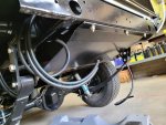
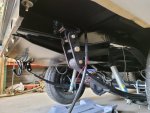
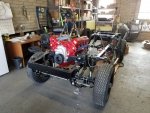
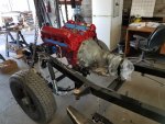
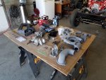
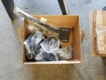
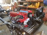
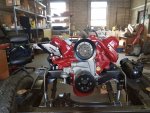
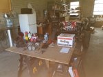
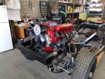
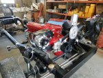
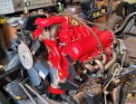
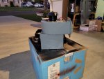
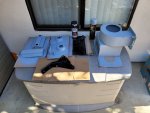
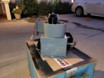
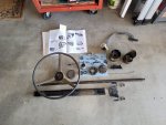
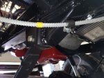
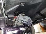
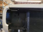
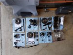
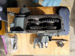
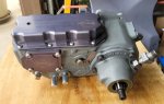
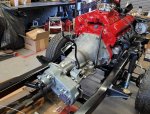
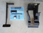
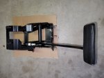
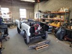
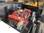
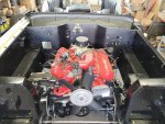
Beautiful !!Finally making some progress. Friday I picked up the rebuilt TF 727 transmission with rebuilt Torque Converter and Balanced & Blue Printed IH 345 with stage II port and polish job with Isky Split Duration Cam shaft. I got the pattern lined up and marked for the torque converter to flywheel mounting. I installed the flywheel to crank with Red Loctite and torqued to 55 ft. lbs. I matted the engine and transmission together torqueing the bolts to 105 ft. lbs. with Red Loctite applied. Installed the powder quoted engine mounting brackets and set the engine and transmission into the chassis. I still need to bolt the torque converter to the fly wheel as I'm missing two of the 5/16" NFT x 7/16" bolts. Next Friday's work is cut out for me as I have a table full of parts to install along with a box full of powder quoted pulleys and brackets.
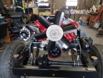
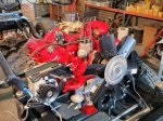
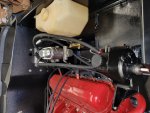
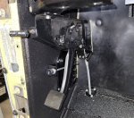
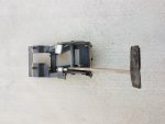
This past Friday I installed the hi-torque starter,
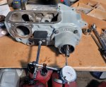
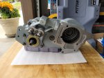
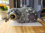
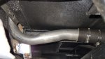
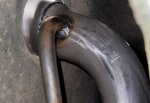
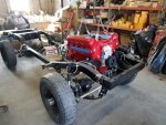
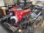
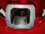
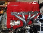
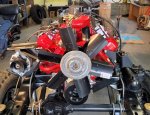
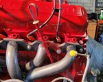
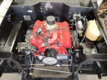
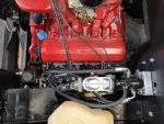
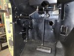
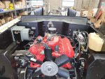
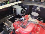
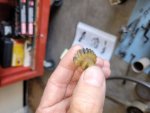
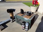
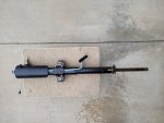
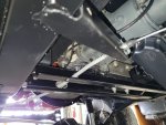
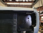
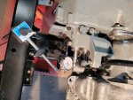
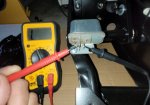
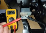
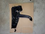
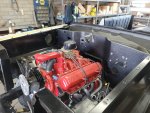
Project is looking great! Glad our guys were able to get you advised on the Dana 20. As for the oil pressure sending unit, you are trying to install it in the wrong hole. On your post, the 4th picture, you can see a square headed plug on the side of the block. There are four of them running along the driver side of the block. Anyone of them will work for the oil pressure sender, but typically it is installed on the second from back, which is a little over an inch away from a 1/4" pipe plug that is a block coolant drain.I'm behind in my posting so I will catch you all up to date. On this day I got the 2-barrel manifold, carb, distributor, coil & coolant temperature sending unit hooked up. A couple of mechanics at work helped me out with fabricating the original dip stick tube to fit between the headers. I am baffled with the new oil pressure sending unit that I still need to install? It has the same threads as the original unit but I can't install either unit as the location in the block where the switch goes has coarse threads and the oil pressure switch is fine threads? Does anyone know if there is adapter that I may have lost/forgot about that needs to thread on the end of the oil pressure switch?
You can leave the valve covers the way they are. Most were installed just like you have it. I'm not aware of any other holes needing to be blocked off on the lower sides of the block. Just the oil gallery plugs, as we have already discussed, and the coolant drains.Hi Jeff, Thanks for the info on the placement for the oil pressure sending unit. You're right, I was going through my pictures and noticed that it is on the drivers side. What through me off is the engine builder put the valve covers opposite of how they removed them. So I was insistent that it went on the passenger side according to the location of the oil fill cap now. Do I need to put the valve covers back how they were originally for better oil drainage to the rear of the engine when adding oil? Also each side of the block has threaded holes that are exposed below the valve covers and above the freeze plugs. Do those holes need to be plugged? I don't recall removing anything from them? Thanks again for the help from your staff and your self.
Your welcome. Thanks for following the project.You're doing some real nice work there. Thanks for the pics.