Switchable Dual Batteries

Matt G

Member
This post is an edited version of the original, which appears in my ongoing project thread At what's now the binder planet site. I've received several inquiries about this dual battery setup from guys wanting to do something similar, so I re-post it here for everyone's info. Mike mayben is the brain behind this system, so any questions should be posted here and I'm sure Mike would be happy to answer them. This setup would be very useful for anyone doing heavy winching, pulling a trailer with a battery of its own, or if you just want a backup power source.

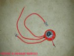
Goodies list: sure power isolator & install kit, marine grade battery switch, 6 circuit fuse panel (for later accessories) and the much-discussed Ford style 4-post starter relay. The battery switch was the real gem of this lot: I sourced it from a boat dealership. It's a very well-made blue sea marine-grade switch which cost me $24.

6137battery_equipment_001.jpg


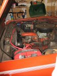
First step, done at home before the install weekend at Mike's place, was to clear some under-hood space for all these goodies and the addition of a 2nd battery. To do this I relocated the windshield washer fluid tank to the center of the firewall, and extended the squirter motor wire to reach the new location:

6137scout_001.jpg


That created a nice hole for the additional battery, isolator, and switch:

6137scout_004.jpg


Once at Mike's place, we scoped out component locations and planned the cabling runs.

I opted to replace all the primary battery hold-down hardware while I was at this since it was so old and grungy - brand new trays under both batteries with new clamping hardware. Then a final check of component locations before we began wiring:
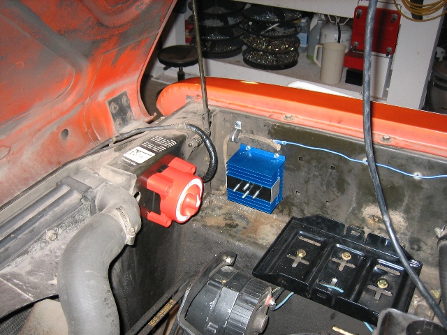
6137dual_battery_006.jpg


Next up was installation of the starter relay. In some ways this was the most intriguing part to me, because the Scout had stopped charging about 6 months ago. A good mechanic friend of mine bypassed the charging circuit by running a 8 gauge jumper from the charging post on the back of the alternator directly to the "+" post of the battery. This kept me on the road, but being the anal do-everything-right type I tend to be, I wanted to locate and rectify the culprit in the charging circuit.

My bulkhead connectors (surprisingly) are in fine shape. But we did find two likely culprits: first, the fusible link wire running into the b.c. From the alternator had blown. There was still some contact, but that seemed to be the clear problem. Also, when I got down low to relocate the wires from the starter motor we discovered that the ammeter-to-starter-post length of the charging circuit was partly melted and moderately corroded at the ring terminal end. Surely these combined were my problem, so we replaced both problem areas with all new wire, jumpered the starter posts properly for the new relay, and wired the relay up:
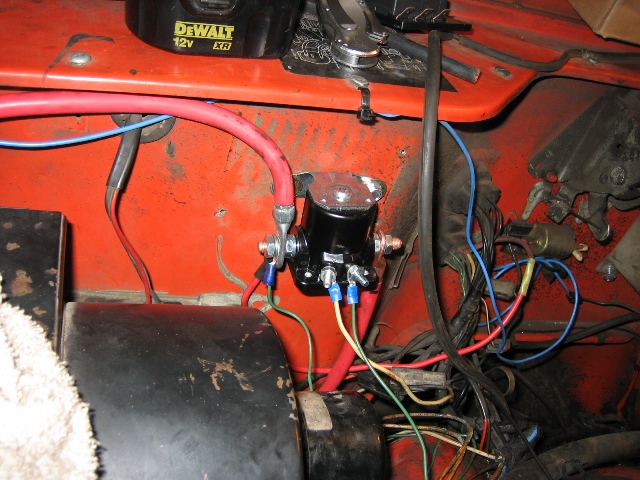
6137dual_battery_018.jpg


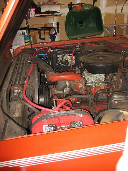
Now the real fun began as we began routing, measuring, cutting, and terminating wires. I replaced all battery cables with new 2 gauge cabling. We also completed a "bonded ground" system, running additional 2 gauge cable from the block to the frame (visible in the second pic below) - something Mike regularly preaches the value of doing. By the end of it we had estimated almost perfectly: every connection was made and almost no heavy cabling was left over.
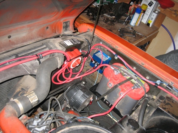
6137dual_battery_019.jpg


6137dual_battery_020.jpg


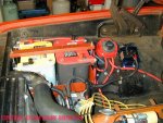
I put a new optima red top in the primary position, and moved my 6-month-old napa battery into the auxiliary position.
attachment.php


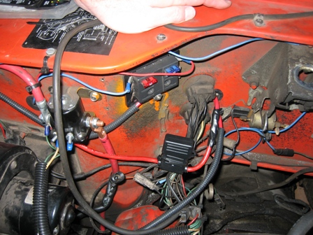
Finally, this shot shows the new 6-circuit fuse panel - 2 circuits currently used: 1 for my cb and 1 for a 12-volt auxiliary power outlet in the dash for charging my laptop computer. It also shows the new charging circuit wiring & maxi fuse - note that I bypassed the bulkhead connector completely. The charging circuit now works like a charm.
new_charging_circuit_001.jpg
 

Attachments

  • IMG_6313.jpg
    IMG_6313.jpg
    58.1 KB · Views: 5,620
Well I thought I would start this thread back up again. As you know I purchased a winch, so I am thinking it would be a good time to install a dual battery system.
First question is there a schematic that I could study for this purpose (winch)?
Also what is the benifit of the isolator, am I right in thinking it would reduce the load on the alternator and factory wiring to the alt guage?

I don't see myself winching hard all day long but I also want it there when it's needed with no worries.

I also have seen that painless wiring kits are available, any thoughts on those?

Just planning ahead and starting a parts list.
Thanks
ron
 
well I thought I would start this thread back up again. As you know I purchased a winch, so I am thinking it would be a good time to install a dual battery system.
First question is there a schematic that I could study for this purpose (winch)?
Also what is the benifit of the isolator, am I right in thinking it would reduce the load on the alternator and factory wiring to the alt guage?

I don't see myself winching hard all day long but I also want it there when it's needed with no worries.

I also have seen that painless wiring kits are available, any thoughts on those?

Just planning ahead and starting a parts list.
Thanks
ron

In my world, the painless products are grossly overpriced but they have the "name". We have near identical systems available here right on the shelf! The "kwikwire" brand from saint wire, a sample of offerings is here:

kwikwire 14 circuit vehicle wiring kit - International Scout parts

As for a schematic for connecting the winch, it simply connects to the battery terminals of the battery that is going to power it...no fusing or circuit breakers. The schematics/instructions for both the isolator and the battery switch are included with the parts and can also be downloaded from the manufacturer's respective websites.

The dual battery system with an isolator is a totally separate upgrade, it's beneficial for any vehicle used in a back-country environment, that has a major sound system installed with high current amps, or is used for towing service where charging an auxiliary battery bank on a trailer is needed. You do that in diy mode, I use the wiring kits for the isolator because locally they are a great value considering the cost of the high current circuit breakers and 6 gauge wire!

The isolator is a much more modern version of what we used to use which was a pair of high amperage-rated, continuous duty relays to control multiple battery charging, either manually, or automatically switched.

An isolator allows a single alternator to charge two (or more depending upon the switching arrangement) storage batteries simultaneously. However...the designated "auxiliary" battery is isolated from the main (starting) battery when loaded. That way, it's not possible to draw down both batteries to the point ya can't start the engine, the crank battery will always be charged if the charging system is operational.

When we add in the manual battery switch, that is allowing us to use the crank battery only for starting/running the primary vehicle. If...for some reason ya discharge that battery to the point it's not useable for engine staring, then ya place the battery switch in the "all" position and ya jump start yourself off the auxiliary battery!! Or...in the case of a winch, you can use the "all" position to parallel both batteries for added ampacity, but you will suck down ypur crank battery in the process.

You can also spend over $300 and install an "automatic" switching system, or operate it from a dash toggle, but that's just one more thing to fail in my world. I've been using the marine-type battery switches for nearly 50 years and they are bomb-proof, who cares if ya gotta pop the hood to switch? Same for rigging the two electro-mechanical relays for isolation, those items are prone to failure in continuous duty usage, just like the relays used in the winch control system.

If you are going to do a multiple battery setup using an isolator, then all batteries used should be identical in chemistry/design and ampacity. If they can be from the same manufacturing "lot" number that is even better!

I thought I was really being smart several years ago when I did my dual battery setup, I mixed a optima red top for a crank battery with an optima yellow top for the auxiliary. Wrong! I now have a $200 yellow top that is worthless because it's not been charged properly in the dual battery scheme. The alternator and isolator cannot charge each battery in a "smart" mode, a deep cycle yellow top needs a totally different charging rate than the red top crank battery. I knew that, but I thought by alternating batteries between crank and auxiliary service, I could overcome that...hell no!! That system has lasted nearly five years, but now the yellow bitch is toast. This system give me three batteries (two on the trailer itself) to run the travel trailer when dry-camped, that will take us about five days without recharging from the tow rig alternator and no chance of draining the crank battery in the process.

For the best resource regarding isolators and similar products, go right to the number one source of "made in the usa" products such as this:

sure power industries

They are the root manufacturer of most all isolator products sold under the various brand names. Stay away from the chinese knockoffs, they are not reliable and the few dollars saved by buying that shit is false economy.

This pic shows my rig right after I fabbed it, it's a pickup of course and it's not practical to set one up this way on a Scout. The optimas were selected for physical size to fit in a custom-fabbed battery mount, they are more than sufficient for the load requirements of my towing/winching package. This pic is before I installed the warn 8274 winch and a homebrew "remote-mount" relay pack for the controller.

I have a similar system in process now for my Scout 80 with batteries mounted on the inner fenders on either side, that one is gonna use optima yellow tops in both positions laying on their sides.

Matt's system evolved from the way I originally set up my pickup, but he had the issue of "non-charging" to contend with at the same time!
 

Attachments

  • Dual Battery Lashup.jpg
    Dual Battery Lashup.jpg
    95.8 KB · Views: 2,968
Last edited:
Thanks for the info michael, but it sounds like my train of thought was running down the wrong track, again.
It sounds like your saying that a dual battery system with an isolator is not necessary for a winch, I understand that a winch connects to the battery posts so maybe I should rephrase my question.
I am installing a winch and I like the idea of having a dual battery so I do not pull the life out of my cranking battery if I have to winch. What would you suggest for an install? Or am I just over thinking the whole deal
sometimes thinking hurts to much:shocked:

you posted as I was typing, I will check out your link.
Thanks

ron
 
thanks for the info michael, but it sounds like my train of thought was running down the wrong track, again.
It sounds like your saying that a dual battery system with an isolator is not necessary for a winch, I understand that a winch connects to the battery posts so maybe I should rephrase my question.
I am installing a winch and I like the idea of having a dual battery so I do not pull the life out of my cranking battery if I have to winch. What would you suggest for an install? Or am I just over thinking the whole deal
sometimes thinking hurts to much:shocked:

you posted as I was typing, I will check out your link.
Thanks

ron

Is a multiple battery setup "desirable" for a winch implementation? By all means! But there are thousands of winches in service that are not connected to an auxiliary battery, but for practicality and even occasional use, I think it's mandatory! Extra expense? Of course, but redundancy on vehicles used in vocational service and off-road is always good! When winching with a single battery, the engine should always be running and use of a hand throttle control helps keep engine rpm/charging current up to help cover the winch load. Otherwise, you can suk down a crank battery in very short order below the threshold for ignition system function and starter spin.

For an initial winch installation, simply plan your cabling runs to the winch with connection to an auxiliary battery mounted somewhere in mind. Then once you have set up a multiple battery arrangement, then it's simple to re-route the cabling.

A winch should not be connected to any GM-type "side terminals" onna side terminal battery. That holds true for optima and optima-type private label agm batteries also. The internal tie bars aren't rated for continuous high current draw, only the top terminals in a quad-terminal battery are.

Doing a dual battery setup has no impact on the oem electrical system other than the alternator charges at a somewhat greater rate if the auxiliary battery is drawn down. But that is no problem whatsoever, the oem 61>63 amp alternator can handle this just fine! If using an isolator with the battery switch, the ammeter will not be connected to the auxiliary system in any fashion, there is no additional load. But....when running with the battery switch in position #2, the load will not register on the ammeter, that is normal and not a concern.
 
Ok now I am back on track or the fog is clearing so to speak.
With my Scout the install will be a lot like Matt picture's above, one on each fender. The hand thottle is a good suggestion. Now all I have to do is start gathering parts. I have some time, my winch bumper build will start this weekend.

Thanks
 
ok now I am back on track or the fog is clearing so to speak.
With my Scout the install will be a lot like Matt picture's above, one on each fender. The hand thottle is a good suggestion. Now all I have to do is start gathering parts. I have some time, my winch bumper build will start this weekend.

Thanks

That's the idea! Don't look at this major electrical system upgrade as a single project, it's multiple interconnected systems that are integrated only because they share batteries.

Every time I do one, it "evolves"! And the imperative deal is the "bonded" ground system with all metallic elements of the entire vehicle connected together at the same ground potential.

Starting off with a matched set of new batteries is the ideal situation, but most of us can't afford to do that with the budgets we have for playing with this stuff. I started off with one optima and one conventional lead/acid battery that was several years old. So did Matt. If your batteries are not optimal, that is not gonna damage anything, it just means ya May not be able to have each achieve their maximum charge level when tested with a either a voltmeter or hygrometer.

My winch has not been operational since I finished the install...it was junker I reconditioned using a "kit" from warn and local-source bearings that warn does not supply. The motor was toast and the control pack missing.

I fabbed a new control system including the remote and the relay pack, and just yesterday finally found new prestolite winch motors that are very affordable, about one-fourth the price of the same motor from warn! The primary use I have for the winch is to operate a gin pole setup that is gonna mount on the front bumper and used around here for moving and lifting schnizz. The motor will be here Friday and I'm getting anxious to stretch the cable! That also means another $165 for another optima red top this time!
 

Attachments

  • remote 2.jpg
    remote 2.jpg
    104 KB · Views: 2,691
One more? The solinoid shouldn't that be a continuous duty type not just a "starter" solinoid? Got a part #?
Hmmmm?, with a manual batt switch why the solinoid? Or is that Matt's remote starter solinoid? If it is I don't need a part #.
See as I keep typing I think I answered my own question :)

I have a good start on the bonding issue, I have read too many problems with grounds and I have been adding/repairing them as I come across them.
I like your control plug! That's just what us old f_rts need when we winch these kids out of trouble:icon_wink::icon_wink:

good luck with the gin pole that sounds interesting with alittle danger involved:icon_wink:

ron
 
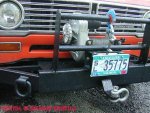
Here's the other side, the relay pack is mounted on a dedicated mount under the hood between the grille and the radiator core support, out of the weather. That way there is only a cable run to the battery of about 18" on the b+ side and 24" on the ground which runs back to the battery, not the frame.

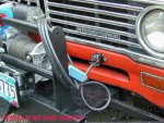
That fairlead is the harbor freight clone of the warn fairlead, absolutely the same dimensionally. It does have nylon bushings instead of bronze bushings but is about 1/4 the cost of the warn item, so if you eat it up, it can be replaced three times for the price of the warn item.
 

Attachments

  • DSCN0001.jpg
    DSCN0001.jpg
    112.3 KB · Views: 2,548
one more? The solinoid shouldn't that be a continuous duty type not just a "starter" solinoid? Got a part #?
Hmmmm?, with a manual batt switch why the solinoid? Or is that Matt's remote starter solinoid? If it is I don't need a part #.
See as I keep typing I think I answered my own question :)

I have a good start on the bonding issue, I have read too many problems with grounds and I have been adding/repairing them as I come across them.
I like your control plug! That's just what us old f_rts need when we winch these kids out of trouble:icon_wink::icon_wink:

good luck with the gin pole that sounds interesting with alittle danger involved:icon_wink:

ron

The starter relay you see in the pics here is for the remote relay addition we do as described in this thread, that is imperative on any IH vehicle:

http://www.forums.IHPartsAmerica.co...pgrade-remote-starter-relay-installation.html

That is the first electrical system upgrade to do!

The "relay pack" for the winch varies according to brand and winch model number from various manufacturers. In the case of the venerable warn 8274, those had a control pack mounted on top inna plastic box that contains four continuous duty relays rated at 200a each. Two of 'em are used in parallel for each motor direction, giving a total continuous duty cycle/ampacity of 400a each direction (power in/power out). Back in the 50's when that winch was introduced, those were the highest ampacity relays available, now they have been replaced by only a pair of 400a continuous duty items.

The "Ford" type starter relay is in no way suitable for any kind of high current/continuous load!!! They will melt down almost instantly when used in a winch app under even moderate pull. Those relays are only for starting motor apps, and even then in only moderate service with plenty cool-down between starting cycles!

Here's the source I'm using for this kinda stuff, including the relays:

db electrical starter-alternator > winch solenoid,prestolite solenoid,universal solenoid,solenoid

A year ago, the individual relays were selling in the $80 range, they have been reduced in price drastically recently.

The more modern warn winches use a solid-state relay setup for their controller.

Your hf winch includes the relay pack as part of the system, no need to add anything else other than the battery connection pigtails!

The battery selector switch, is simply a means of controlling which battery feeds what! Or both can be used in parallel (that is how you can "jump-start" your self by only changing the switch position to "all).

I wire the second battery feed from the alternator to the battery through the selector switch so that it has a wire run of only 6" in my case. Juice is juice, no matter where ya tap in! A 50a circuit breaker protects the feed to the auxiliary battery, that is an item that is very expensive if ya don;t source it with the surepower install kit.

This pic shows the battery selector switch and how it's wired. I use the side mounts on the batteries for "normal" loads, the top posts only on the yellow top feeds the winch. The cable with the ring terminal goes to the "remote" starter relay that operates the starter motor. The short 6 gauge is the feed from the isolator, through the 50a circuit breaker, and out to the auxiliary battery only (switch position #2), that is the modification I do so that I don't have to have a long 6 gauge wire run to the second battery. We did Matt's in a very similar fashion, but his blue sea switch is much nicer than the perko and it wires a bit different underneath.
 

Attachments

  • DB14.jpg
    DB14.jpg
    56.4 KB · Views: 2,671
Excellent info, just what I need. I have searched the surepower isolator and I have found 2 different sizes 120a and 160a, what have you used? I assume since I have a stock 63a alt the 120a would be fine, correct? Because we are talking stricly charging current passing through.

Ron
 
ron,

my isolator is a max 95 amp model.

Good luck!

I believe the 95 amp version has been discontinued though they are still found everywhere on the shelves!

The 120a version is just fine, far more ampacity than you will ever need.

Also...regarding the battery selector switch, the one I used does not have the "field disconnect" feature. Therefore you never move the switch while the engine is running. If ya do, you will toast the diode block in the alternator.

The various battery selector switches that do have the field disconnect feature May be "switched" with the engine running, though you never turn the selector off with the engine running, bet you can understand why!

The install kits that surepower packages include 6 gauge wire, major overkill that is great! The oem shit is a 10 gauge circuit, so I rewire the oem charge lead with 6 gauge also. Crimping 6 gauge insulated or copper lugs can be a bitch if ya don't have a texas aggie toenail clipper.
 
I use a punch and a hammer to crimp mine terminals. Then follow up my melting solder to fill the gaps. Then a piece of heavy duty shrink wrap
 
Mm re:install kits that surepower packages include 6 gauge wire, major overkill that is great! The oem shit is a 10 gauge circuit, so I rewire the oem charge lead with 6 gauge also. Crimping 6 gauge insulated or copper lugs can be a bitch if ya don't have a texas aggie toenail clipper.
1972scoutii re: switchable dual batteries
I use a punch and a hammer to crimp mine terminals. Then follow up my melting solder to fill the gaps. Then a piece of heavy duty shrink wrap

Thanks guys, but I have access to a ne cornhusker toenail clipper, much better than those texas ones:icon_rotate::icon_rotate:

ron
 
Well my dual battery system is installed! Everything looks like it working fine, but I do have to verify one thing. I will run through my connections as to what I did then the question.

First I installed a remote started solenoid connections are:
removed the 3 wires on the bat+ terminal on the starter, the bat cable, the 10ga blue to the bh connector and a small green wire(?) and moved them to one side of the solenoid. Both terminals the "s" and the "r" terminal wires moved the the corisponding solenoid terminals. That part seems ok.

Now the sure power isolator instructions say to remove the bat+ wire (10ga blue to the bh connector) on the alternator and wire a new 6ga to the "a" post on the isolator. Then I took 2-6ga cables and connected them to the "1 and 2" terminals on the isolator and connected the other end to the bat "1 & 2" terminals on the bat selector switch with the new battery + cables. Both batteries are charging, verified with a volt meter. Thats good!

Now the question, where should the 10ga blue wire that came from the bulk head to the bat+ terminal on the alternator go?
Of course with out it connected the alt meter on the dash does not work, and if I connect it back to the alternator the guage works but it works on both position 1 & 2 of the selector switch.
I read were it should not work in the bat 2 position of the selector switch. Also when connected back to the alt b+ I lose the "off" function of the bat selector switch.

What am I missing with these 2-10ga blue wires?
Oh, the ignition switch does shut the engine off with the bat selector switch in the off position.

Thanks
ron
 
Hi ron,

Mike will get on here and correct any errors I post in short order, I'm sure. But mine is wired a little different than what you describe, which seems pretty clearly is the source of your discrepancy in functionality.

The cable off the "1" post on the iso is The stock 10 ga. Cable run to the bhc. The "1" post cable runs into the stock ammeter (assuming you're still running one) then comes back out the bhc and attaches to the remote starter relay.

So you can think of it this way: remove the stock cable (circuit 2 on the oem wiring diagram) from the back of the alternator and run a new cable from the alt to the "a" post on the iso (as you have done.) then re-attach the original circuit 2 wire to the "1" post on the iso, and you're off & running. So you're basically just putting the isolator in series with the original oem circuit 2.

Now Mike: what'd I say wrong? :crazy:
 
Matt; that makes it clear, what your saying is the #1 post on the isolator is the 10ga it runs though the oem alt gauge comes back out then connects to the input post on the remote starter soleniod, thats where the connection to bat+ on batttery #1 is made.
I added an extra wire from post 1 on the iso sraight to + post on battery 1 (via bat selector switch) which is not needed, that's where I screwed up.
Thanks
ron
 
Last edited:
Ok I got the 10ga blue hooked up right now, but only one item still does not seem quite right. With the engine running,, when I turn the bat selector switch to "off" the engine keeps running. Which tells me I am running off the alternator alone, that does not seem quite right, but I May never use the "off" position. Maybe thats normal, like disconnecting the battery with engine running.

Other than that the system is pretty nice. Now if I can ever get my borther in law to finish my winch bumper:icon_xd:. I guess getting married is more important than working on my bumper:crazy:

thanks for all the help, patrs list, install info and touble shooting.

Ron
 
I believe the 95 amp version has been discontinued though they are still found everywhere on the shelves!

The 120a version is just fine, far more ampacity than you will ever need.

also...regarding the battery selector switch, the one I used does not have the "field disconnect" feature. Therefore you never move the switch while the engine is running. If ya do, you will toast the diode block in the alternator.

The various battery selector switches that do have the field disconnect feature May be "switched" with the engine running, though you never turn the selector off with the engine running, bet you can understand why!

The install kits that surepower packages include 6 gauge wire, major overkill that is great! The oem shit is a 10 gauge circuit, so I rewire the oem charge lead with 6 gauge also. Crimping 6 gauge insulated or copper lugs can be a bitch if ya don't have a texas aggie toenail clipper.

Duh!! I should comprehend what I read.:incazzato:
ron
 
Man I really scruud up and simply did not see your posts ron!

Then while responding this morning, an accident downriver wiped out all electricity and cell/landline communications in the entire valley, we just got dsl back a few minutes ago, cell service is still out. I did manage to save this response this morning after I-net access died.

But Matt covered everything in well-spoken english and dam he did a guud job! And so did you!

Yawl need to know...about five years ago when Matt accosted me at the Binder Bee for some "help", he didn't know which way to turn the key to start a Scout II! All he knew was that once a week he traded dollars for gasoline somewhere, and since he's in orygone he didn't even have to git out of the cab to pump it!

Matt helps out all kindsa folks 24/7 with healing in their lives, but he dam shore couldn't heal any thing that required a hand tool.

Fast forward five years, dude is dam near a full-fledged journeyman meekanik! And his wife and kids encourage his continuing education so in the future he can add to his repertoire now he's taken up marine mekanikin' too, on mercury outboard carburetors no less! He'll need that when noah's flood comes back around after them polar ice caps finish meltin'.

Back to the subject...there are several ways of incorporating the "switchable" dual battery setup, ya just gotta have a basic knowledge of the charging system and the design limitations of the IH-produced stuff in particular, mainly the bulkhead connector issue, the bogus "ground" system, and the use of the ammeter as the primary current feed for all electron distribution.

Use of the marine-type battery selector switch is somewhat unique in our world, most folks want some kinda dash control or "automatic" function for that, but not me, I can still open the hood and handle a good old hd mechanical switch without the gummint doin' it for me! And $40 for that switch instead of $350 for the "automatic" crap sure helps in the budget department!

Another piece of advice...swap back and forth between the two batteries monthly to exercise the auxiliary through a few discharge/charge cycles (engine starting). "wet" type batteries (whether flooded cell or agm) need exercise and that also tells ya everything is working properly. If I had done that I would not have allowed my optima yellow top to go bad to the tune of $185 after only three years.
 
No problemo Mike, Matt was a big help! He cleared the fog when I was wiring the iso, I was going by the surepower wiring instructions and did not combine the oem connections (duh). But we gottr done!
I will try to post some pics in a few days, I am going out of town on work, looks pretty much like Matt's except for a custom battery tray. I tried one like Matt's but did not like the way it had to be held an inch away from the vertical wall of the inner fender because of the hold down. So I built one that the hold down is length wise to the battery and the tray bolts to both the horizontal and the vertical wall of the inner fender. It made the battery more solid in the tray and the battery does not stick any further into the engine compartment than it has to.
I aslo used ring terminals on everything with marine grade battery post connectors (wing nuts). The terminals are rated for the 2ga wire so they should work, but May require a little extra maintenance to keep them clean, we will see.

Good tip on battery exercise though, I also used a yellow top for my 2nd battery I have plans to install one for the crank battery also.

Off topic; you mentioned Matt's wife being supportive, man my wife was actually turning wrenches with me. She handled the relocation of the windshield washer res (did a good job to) and helped me put the radiator back in the 75. I even caught her on ebay looking at scouts:cornut: who knows we might be looking at a his/hers Scout family in the future. Not braggin but it was a first in my shop.

Thanks
ron
 
Last edited:
These lifepartners just gotta warm up to this oldiron stuff ron! And it helps if they don't experience too many breakdowns on the road! We look at that as an adventure, wimminfolk look at it as a disaster and crisis!

Running dual yellow tops is an excellent idear, wish I'd done that looking back when I invested in the optimas. The deep cycle yellows serve just fine as crank batteries, especially on the IH stuff since cranking requirements are so mild! My mistake (I thought I was smarter than johnson controls!) was in mixing the chemistries!

Johnson controls clearly advises to not mix batteries of different chemistry in multiple battery systems. And the isolator folks all advise using multiple batteries that are new and "matched" (meaning they carry the same "lot" number code).

The alternator can only produce one "charge rate" and that is based upon the most needy battery in the system. A single alternator can't charge at two different rates, and the isolator only prevents a low voltage battery from discharging a "charged" battery in an attempt to equalize charge level chemically.

In my case, I made the sitch even worse! I had a red top and a yellow top combined under the hood, the proper "terminal voltage" between those two chemistries is significantly different as to what constitutes a fully "charged" battery.

Then...when the trailer is connected, that added into the entire charging system, two additional batteries, one was a conventional flooded cell deep cycle, the other a red top. Total wrong combo! So charging four batteries off a single alternator through an isolator is really dumb! Yes, the alternator is perfectly capable of doing this (and did so for nearly three years), but only the red top crank battery was ever fully charged at any one time when driving down the road.

When the trailer is plugged into shore power, the on-board charger charges the house batteries at the proper "rate", but since there is no isolator on the trailer from that end, then the mismatched batteries also would not allow the red top to fully charge as the chemistries are significantly different!

In that case, the only thing I did right when the trailer was plugged into shore power, was to disconnect the trailer harness so the trailer charge could not attempt to charge the tow rig batteries. To run the four battery setup, I should use two isolators, one mounted in the trailer system.

When I hit the lottery, I will have four matched optima blue top sparkers! Two under the hood, and two in the trailer...that is the ultimate "dry camp" weapon! That's about $800 in batteries right now locally! That gives me three batteries for the trailer, and keeps the crank battery out of the loop for discharge for long-term dry-camp.
 
Back
Top