Crank Trigger Ignition System

Michael Mayben

IHPA Tech Moderator - Retired & No Longer Online
While the engine project described in this thread has yet to get under way due to budget constraints, I have been gathering and prepping parts for the package:

http://www.forums.IHPartsAmerica.com/gas-engine-tech/1144-ultimate-IH-fourbanger.html

The ignition system for this motor will be a "crank trigger" design. The distributor will be completely eliminated, each cylinder will have a dedicated coil.

Major components to be used for this system will be:

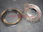
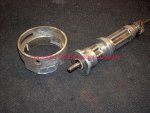
1) msd "universal" crank trigger assembly fabbed to mount to the timing cover for the I-4 motor (machined to fit oem I-4 crank hub).

2) msd 6 series cd ignition box.

3) n=4 low primary resistance ignition coils (yet to be determined).

4) msd 8979 ignition controller (laptop programmable for advance curve for each cylinder and firing order).

5) modified distributor to serve as oil pump drive.

The advantage to this system will be super-accurate ignition timing that can be "adjusted" and optimized for each cylinder through the use of the msd ignition controller and it's associated software. Since the distributor is eliminated, so are timing variations throughout the rpm range due to distributor wear and tolerance. And ignition timing May adjusted on the fly if desired to cope with varying fuel quality/octane and operating elevation.

Details to follow...
 
The flying magnet wheel is a universal-fit item that will have to be machined to fit the oem I-4 crank hub shown in this pic. The wheel will mount between the pulley and the machined boss on the hub. A second pulley will be added to the stack in order to allow any future drive position, say for a ps pump.

Once the crank hub assembly is done up, then it will be combined with all the other engine components involved in a dynamic balancing operation for the hybrid stroker motor.

A very similar hub is used on some sv applications as well, including 266 and 304 motors.
 

Attachments

  • Crank Hub.jpg
    Crank Hub.jpg
    170.4 KB · Views: 1,115
Here's a typical set of msd assembly instructions for setting up a crank trigger. Because there is not a dedicated "kit" available for the I-4/sv engine apps, some creativity is gonna be necessary to mount the trigger unit in the most desirable position.
 

Attachments

  • 8655_MSD Crank Trigger.pdf
    138.2 KB · Views: 664
The sparks will be provided for by using a plain old msd "6 series" capacitive discharge ignition box. This box is then interfaced with the ignition controller.

I don't like the idea of an "integrated" electronic system, I'm much rather use individual components that can be plugged in to talk to each other and if something fails, then it's much simpler to diagnosis and replace a failed piece than an entire system.

And the 6 series msd box May be used with virtually any engine/system known in a stand alone mode.
 

Attachments

  • 6420_MSD 6 Series.pdf
    1.8 MB · Views: 769
And here's the brain for the whole lashup.

A programmable controller with cabling and software (software is freeware available for download from msd). Since there will be no distributor, ya gotta have a way of setting up and operating the ignition advance curve for operation throughout the rpm range of operation.

The controller also establishes the firing order for the system, so once all components are interconnected, it would be possible to move this stuff around on any spark-ignition engine app in the future.

The software allows a lotta stuff to play with so it'll be a challenge to get this system dialed in!
 

Attachments

  • 8979 MSD Ignition Controller.pdf
    937.6 KB · Views: 972
the flying magnet wheel is a universal-fit item that will have to be machined to fit the oem I-4 crank hub shown in this pic. The wheel will mount between the pulley and the machined boss on the hub.

Once the crank hub assembly is done up, then it will be combined with all the other engine components involved in a dynamic balancing operation for the hybrid stroker motor.

Mm,
if you need some machine work on the pick-up wheel you can send it down and I'll take care of it for you. I'll bore the diameter and put the hole pattern in it.
 
So if the distributor is eliminated, how do ya drive the oil pump onna I-4/sv motor???

Here's my homebrew solution, it's not finished but can be used as is for getting the bugs out.

The top of the modified body will be turned down in a lathe and a "cap" made to be pushed over the top and sealed with an "o" ring. There is a plugged access hole in the side of the distributor that will be drilled through to the top bushing and a grease zerk installed.

This distributor started life as a Holley gold box unit that had major internal rot. The body and the shaft were usable, none of the rest of the pieces are salvageable. I will not waste a rebuildable distributor for making an oil pump drive, only trashed units will become donors.
 

Attachments

  • Pump Drive for Crank Trigger.jpg
    Pump Drive for Crank Trigger.jpg
    129.4 KB · Views: 1,182
mm,
if you need some machine work on the pick-up wheel you can send it down and I'll take care of it for you. I'll bore the diameter and put the hole pattern in it.

Ya read my mind well in advance!

The hub will also needa speedee sleeve done, I'll handle that here. And I'll send down an extra hub for yourself if needed.

The one in the pic is an oem unit for a 152. The hub is still on my operational 196 so I don't wanna pull it for comparison of "mass" yet. But I do have a couplea more 152 hubs we can use.
 
The 152 and 196 use the same hub #863-718-r1 and I have one to use for measurement purposes. I suppose the wheel needs to be clocked to referance tdc #1. I'll need the info you have in that regard. I'll be running a magneto so I won't need a hub change.
Just send the pick-up wheel.
 
Michael, you know I am watching this with great anticipation...
A couple of questions. (1) what made you decide on a coil per cylinder (cpc) setup rather than crank triggered, single coil system using the distributor to route the high tension energy? (2) a cpc (as opposed to "wasted spark") system will require some form of cam timing input, also. Have you decided on how that will work?

Semper FI,
charlie
 
michael, you know I am watching this with great anticipation...
A couple of questions. (1) what made you decide on a coil per cylinder (cpc) setup rather than crank triggered, single coil system using the distributor to route the high tension energy? (2) a cpc (as opposed to "wasted spark") system will require some form of cam timing input, also. Have you decided on how that will work?

Semper FI,
charlie

Pure bling charlie! No plug wires except for short ones from each coil (depending upon which coil set I end up using).

Regarding the wasted spark syndrome...the programmable controller is "supposed" to handle that detail, I haven't fully diddled around in the software yet to see what the setup parameters are though...the stuff is installed and updated though on this pooterbox.

But you are correct...if a gutted distributor is retained (only for spark energy distribution and oil pump drive), then only a single coil would be used and it would appear oem except for the flying magnet set up. And somewhat less cost overall.

But if needed once I get into the fab work/software, the addition of a cam position sensor won't be any biggy.
 
Michael,
I was bored so I and measured up a 4 cylinder hub. I banged out a drawing just in case someone wants to machine the hub pattern in something like a crank trigger wheel? :dita: you would need a mill preferably with dro's. Start by indicating the center hole and set the x and y at 0.0000.

I added a second set of holes indexed 45 degrees so a better choice of pickup locations is available. I think this would make the setup easier.

For reference the dimensions are as measured and accurate to my hub to +/-.002. Usually IH designed to fractions and the measurements are a few thousands off the fractions. Probably normal manufacturing tolerances.

P.s I hope you and dave w got the fe top end all put together.:winky: like I said I'll be listening for it next week end.
 

Attachments

  • IH 4 CYL HUBPRT.jpg
    IH 4 CYL HUBPRT.jpg
    57.3 KB · Views: 1,088
Last edited:
Shit man...ya already done the math!!!!

Soon as the ss check comes, I need to order in a blank wheel! Stand by!

Have ya got any words of wisdom about where to actually locate the mag trigger unit? I'm gonna use the "adjustable" version of course and want everything to fit onna stocker since there is plenty space down there. I've still got a mule 152 onna stand and can do that mount-up any time. Hell...I might go ahead and try this out on the 196 in the pos rig now to see what happens??

Dave and Todd (it's his motor) got the heads done last weekend while I was doing carol's rehab on her rental unit. Todd bronzed all the guides and cut 'em for the positive seals, the spring seats were cut for the aftermarket springs, four new seats installed, six new valves, and two replacement rocker shafts to go with those forged isky rockers. I was re-surfacing the rocker pads when you called!

Dave later dropped by and installed the valve train and then did the initial lash adjustment per the isky specs, not for Ford oem. Dave always shows up at grubthirty...but then he also works real cheep when he's here and food is around! Todd's now gotta $1400 pair of good part number "352" heads with trick springs shimmed to perfection, chromo retainers, bronzed guides, bake and blast, all machined surfaces lightly surfaced for flatness, etc. For about $325!!!! The springs/retainers were leftovers from a sprint car motor that only runs two weekends and then gets "built" again. They did most all the work over two saturdays at dave's shop, but farmed out the cleaning, surfacing, seat install/cut, to a local machine shop. Each valve position/spring pack was shimmed and all seat pressures were matched while Todd stood back out of dave's way!

We got the motor fully built Saturday nite, I hung it from the hoist last nite for final paint work and I'll button on the clutch and tranny tomorrow. I also built an oem distributor for it Saturday, the carb is a superfresh Holley 80457 I'd already prepped. I've got an oil pump drive installed so I'm gonna run it off the drill motor for pre-oil possibly today, it's got a new melling high volume/pressure pump in it so I'm anxious to see what we get!

Once the rig is put in dd service, then we'll upgrade the ignition system accordingly. Todd found a much nicer set of truck headers (full flange with adequate bolt clearance) so we'll fab the exhaust next weekend after the motor is sitting in the rolling chassis where it's gonna get broken in...Todd still hasn't decided "which" body is going to drop, but he's still leaning towards the '66 f100 he's driving now. The chassis is a '75 or so f250 "highboy".

Dealing with the Ford has been much more fun that building Todd's sod (son of duckblind)...a Scout 80 body onna Scout 800 chassis with sii axles, ps, and a 345/727/d20 stuck in the hole! That will be the last sv motor we ever stuff inna s80...no future in doing that kinda abusive shit! And when he see's how these stroker 152 motors spin up, he'll be sick!
 
Last edited:
shit man...ya already done the math!!!!

Soon as the ss check comes, I need to order in a blank wheel! Stand by!

Have ya got any words of wisdom about where to actually locate the mag trigger unit? I'm gonna use the "adjustable" version of course and want everything to fit onna stocker since there is plenty space down there. I've still got a mule 152 onna stand and can do that mount-up any time. Hell...I might go ahead and try this out on the 196 in the pos rig now to see what happens??

I was bored and I had 3 fingers of single malt scotch in front of me. No telling what one can git done under those conditions. :gringrin:
I would fully mock the motor with all accessories before trying to decide on a trigger location. I added the extra hole pattern so you would have more options. I like the lower quadrant personally. Nothing but air down there, also you have the pan rails to use as a foundation to mount the bracket.

I think debugging on a known good running rig first is a good idea. You can make all of the necessary mountings and brackets, debug the installation and timing. Then simply bolt it on the new deal.
When you first fire the new motor you want it to run right and immediately to break in the cam. You can't fart around with it it's gota run now. But you know that.:smilewinkgrin:
 
I hadn't thought about the pan rail for a mount point. I can fab bracketry for that easily now and then just bolt the pickup assembly to the bracket. Good idea!

I'm with ya on the "break in the motor" stuff as soon as it busts off.

I actually have in progress a "make run ignition system inna box" that I can use for recovering dead dawgs when need be, just stuff a fresh distributor in the hole, use a jump battery to connect the fanceeazz "hot wire" ignition system (bypassing all vehicle electrics) and starter relay to a hopefully working oem starter assembly, and hit the button.

Same for slapping onna fresh 2v carb (on an adapter if need be) and running from an external tank off an electric pump powered from the portable ignition box.

If a deadawg's got any compression at all (and not locked up), it'll crank so we can listen to that sweet lifter rattle!
 
Back
Top