why 10si alts for S80's and not the 12? Mayben?

Plug Ugly

Member
I have read the great info that Mike m. Has written, and started doing some alternator research.

Why the 63 amp 10 si over the 94 amp 12 si? They are the same size/mounting pattern arent they?

This would be for a generator upgrade on a 61 80. Figure, I have to rewire it all anyway, so why not go bigger? Is it just that most people wont need 94 amps, or is there another reason?
 
I would have thought that michael's write-up would have mentioned it.

From what I have "read", I think that the stock ammeter is the "weak link". It cannot "handle" 94 amps.

The "stock" hd altenator is 61 amp, so the 63 amp altenator is ok.

So, in your "rewire", you need to remove the ammeter to use the 94 amp altenator.

I am sure michael will reply with the complete / more correct answer.
 
Iirc, plug has a 61 s80 so no amp meter.

Plug I suppose if you wire it right(wire gauge) the 12 will be ok. Why do you need it though? The 152 will struggle to maintain idle speed while driving the 12 loaded. No real devices on a Scout 80 that will consume 744 watts the 10 will supply let alone the 1130 watts the 12 will supply.

While limited I still have the 37 amp alty on my 65 and dont need more. Jmho


Robert
 
No real reason I use the 10si other than they are cheeeeep and they fit all my stuff I got around! Only one spare kept on the shelf with pulleys swapped around as needed. If we're off onna trail run with others, then someone always has the right spare if needed.

The output rating of these units is a peak rating under ideal conditions for about one minute! Then output goes way down because of "duty cycle". A "typical" quality 10si reman (63a version) will produce a max of about 40>45 amps continuous when called upon...that depends upon the quality of the internal components used in the reman process, that can vary tremendously! The longer it tries to produce at max output, the more the output falls off.

In my beater I charge four batteries (three optima and one oldskool deepcycle) going down the road, one is isolated as the "crank" battery, the other three can power the trailer in dry-camp mode for three days, two people and dawgs. All off a "lifetime" reman 63a 10si...however the starting/charging system is highly "optimized" with 2 gauge cabling and 6 gauge charging wiring, through a 50a circuit breaker off the isolator. Oem cables are 4 gauge, with 10 gauge charging circuits and feed to the ammeter.

In that scenario, only the crank battery is "in" the ammeter circuit so that it's charge/discharge can be monitored continuously.

This business about a "high output" alternator taking out the oem ammeter on fullsize and s800/sii is not rooted in reality! The bulkhead connector on those rigs is the weak link, not the ammeter. Of course, the ammeter wiring must be up to snuff, not rat-chewed, tight/clean connections, etc. If that was a problem, then no manufacturer would have ever incorporated that type charge-monitoring system (or marine manufacturer for that matter). But reality is that ammeters were the most common system for decades, and only eliminated due to cost considerations and the dumbing down of passenger vehicles. And proper charge monitor inna motor vehicle involves the use of both an ammeter and a voltmeter!

If someone is concerned with a traditional analog ammeter, then a shunt May be used, or a modern digital-type "multi-meter" which uses an inductive pickup to monitor both current and voltage in the charging system.

Eliminating an ammeter does not reduce the total amount of "current" running around under the dash! The electrons are still there! The total current flowing at any one point is dependent upon which and how many loads are in use. If you simply disconnect the ammeter + and - connectors and tie them together, the loads are still there, the ammeter simply will no longer function. If ya don't want all them electrons under the dash, then ya will have to move the fuse panel outside the passenger compartment! The distribution system must be fed with current to feed all loads, same as in a residential service panel.

I've heard all the horror stories regarding ammeter "meltdown"...but never seen any proof the ammeter was root cause. Even if the ammeter itself is heavily damaged, the one's I've seen were caused by poor connections, not the ammeter itself. But every one of you that is running an oem IH bulkhead connector on any light duty vehicle (including a s80) can pull it apart right now and find damage! Most of ya have already delt with that in some manner.

Regarding the s80 firetrap...the oem electrical system had no fused circuit protection whatsoever other than "maybe" a fuse or a circuit breaker on the headlight switch. And if equipped with an oem heater, a fuse for the blower feed. Even a dam farmall cub tractor electrical system was far more highly engineered!

I'm throwin' up a jpeg of a very simple distribution system like I use for total re-wire on s80/s800 rigs. Not saying this is the best way, but it's very cost-effective/simple and each of the fuse panels have an ampacity of 130a which will never/ever be used! Just an example for the sake of this discussion, there are many different ways of doing a re-wire from scratch! This distribution system is infinitely expandable for additional loads.

This shot is from a very early stage of development of my own s80 project, it's since been cleaned up considerably and optimized. A voltmeter is incorporated with the oem idiot light used to tickle the 10si into charge mode instead of using a resistor wire as found on fullsize and sii systems. I used lowbucks aftermarket gauges which will be upgraded to include an ammeter in the final version. A dual battery system will also be stuck under the hood, an essential item in my world for backcountry travel!
 

Attachments

  • S80 Distribution.jpg
    S80 Distribution.jpg
    91.3 KB · Views: 497
Last edited:
Thanks for the informative reply Mike. I have read your article that you emailed, and its very well done.

My plan is to eliminate the ammeter anyhow. Im just starting this build, and at some point, it will get a Ford 351, rock lights, stereo, york air compressor, dual winches, etc, etc. So my wiring will be imilar to your layout, abut larger cables where needed (I have a lot of 1/0 lying around). Im just trying to get this thing to run for a year or so while im doing the body mods and clean up (plan to stretch the front fenders 4 to 6 inches and the rear like 8 to 10 with a wheel base of about 110i to 115)

the price difference between the two is only like 20 to 40 bucks unless I am mistaken, so was just thinking ahead.
 
Hey micheal, I did have one more question. In your wirte up, you used varying color codes for your wires. Do you have good source for oem color schemes for wires? Delcity and the like have basic colors, unless I missed it.
 
The only reason I used "color code" was all the wire was either "scrap" or what I had on hand. And I've got a great source for wire at prices from the 80's still, but only if ya don't care about color! And that spread sheet evolved over several different installs of the system

the next one I do from scratch will use black for all ground/return runs and red for all feeds/loads, numbered of course!

The "wire run" and numbering system are my own...that evolved in the order in which I originally ran the wire runs. "numbered" wiring harnesses/wire runs are what IH and many hd truck manufacturers used/use. But I did not try and replicate any of the original IH wire runs, I basically use standard marine practices.

As additional loads are introduced when expanding the system, then it's simple to add the wire runs with the appropriate I.d. Number.

One system we've done used only red wire in several different gauges, this was scrap obtained from a major backcountry firefighting rig manufacturer locally, they discard any length of wire under 20ft. Or so in length.

The only color code used in my wiring system is the turn signal switch, because I use the oem switch when possible and it was "color coded" from the manufacturer and interfaced with numbered wire runs at the point of vehicle assembly. In the case of the Scout 80 signal switch, there were two entirely different switches used...and many vehicles had no turn signals as that was an option in the beginning.

Oem wiring systems use wire gauge that is barely sufficient for the load. In the case of IH light duty stuff, the wire gauge in nearly every run is insufficient. The bean counters determine stuff like that, not the engineers. And the never ending quest for weight reduction in modern vehicles plays heavily in that scenario.

IH used only a horn relay in their systems, the lighting systems used no relays and wire gauge of insufficient ampacity (and switching devices also), so that poor illumination quality is the second most crappy electrical issue after the shitball quality bulkhead connectors they used!

In my systems I also use no relays (except for the horn) and the starter, that keeps things very simple and eliminates many points for potential failure. I use wire gauge that is way overkill, along with switching devices that have max ampacity for their intended use, thus no need for relays.

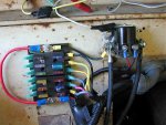
Del city is a good source for supplies, but from now on I'll be using these 12 circuit fuse panels from blue sea (marine electrical components), I have a local source for those also:

st blade fuse blocks - blue sea systems

Same for the blue sea battery switches. I use the isolators for the multi-battery systems from these folks:

sure power industries

The saint wiring system marketed through ihon is a very cost-effective route to go (14 circuit version)! Extremely high quality stuff and far superior overall to the over-priced mess from ron francis, painless (my last choice in anything!), etc.

14 circuit vehicle wiring kit - IH Parts America Scout
 
One "tool" I'm currently gathering materials for is a complete electrical system mounted inna jiffybox to be used in vehicle recovery. Typically rigs that have set for a period of time and have all kinds of "issues"!

This box will contain a complete ignition system (except for distributor) that will operate from an external storage battery that will be part of the kit. No need for the charging system on these old dogs, they''ll run just fine for awhile on "total loss" electrics.

This allows the engine to be cranked over carefully during the pre-lube process without needing the vehicle key or any other device, but hopefully a starter that is operational! It will incorporate a points distributor that is fresh and I'll simply rip out the unknown and stick the good one in the hole.

Jumper cables permanently mounted will connect the "portable" battery to the starter through the jiffybox. Of course a "remote" starter relay/solenoid will be part of this deal, and use a separate starter switch and ignition switch!

Doing this eliminates any possible po virus crap, punky ballast resistor/resistor wire, etc.

More to come on this subject!
 
No, but what I do need is a fuse panel with a spot for flasher relays like found in the variety of wiring kits. I cant seem to find one of those.
 
Back
Top