


mjolnir
Member
Getting ready for a long planned fabrication job…… .wait! I know what you’re thinking but this is the right forum, bare with me and we will get there. I’m not a fabricator, I have seen some on my tv; guess I don’t have enough tats, or talent. But I know of a very talented one (no tats) who is taking on the job.
My role is design, materials procurement, step and fetch and let’s not forget financial. But if I’m involved in a project there has to be wires, yeah! And relays make it all the better. Make that more better! In typical cart before the horse fashion I started with an idea for some electrical bling………………….wireless control!!!!!!!!!!!! Yeah that’s the ticket!
not knowing anything about wireless control I said to myself who do I know that knows about wireless? Of course! I immediately placed a call to catherine zeta jones. michael answered but said she couldn’t come to the phone right now. Being left to my own devices I hit the internet (thanks al!)
 and in short order I purchased a wireless control kit.
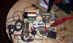
In a short few days the kit arrived and I eagerly dove into it. The module has 17 differently colored wires (drool) and a three page instruction sheet. The first two steps were to cut into the parking light circuit and then the starting circuit. Right there I put a halt on the project. It didn’t sound like something I wanted to do in my driveway in nov. So taking two steps back I decided to see if I could figure it all out on the workbench in the comfort on a nicely heated garage. In short order I threw together this bread board. Part 1 was simply to get a relay to close with a hard wire button….ok, no problem. Part 2 was to get the relay to closed with the key fob (button 3)…no go! At this point it was time to break out the meter. My favorite meter is a cheap radio shack analog multimeter I bought about 35 years ago. Who knew it would last this long? I’ll reach right across both of the digital meters and pull out my r/s meter every time.
The challenge at hand was to fine a negative pulse from one of the wires when k/f button 3 is pushed. Using the meter I was able to find a pulse from the blue/white wire but only from k/f button 1. The instructions clearly lay out that the brown/black wire should work with button 3. after reprogramming the k/f a half dozen times or so I walked away and took the instructions into the house and sat in my easy chair to reread them.
Ok, the instructions mention the module output is a 500ma signal.
 ok here it comes………………….whack!!!!!!!!!!!!!!!!!!!!!!!!!!!! Hitting forehead with heal of the hand (told you we would get there). so I rush back to the garage and attach the brown wire to the relay and hit k/f button 3………..clack! Goes the solenoid, clack!, clack!, clack! I immediately call the wife to come into the garage. Watch this honey! Clack!, clack! Look one hand behind my back, clack! Look between my legs, clack! Look…………….then I notice she has already gone back into the house. Clack! Clack! Anyway.
The gist here is don’t expect an analog meter to show you a reading from a 500ma short duration pulse. The mystery remains as to why the blue wire did show a reading. That led me in the wrong direction. I’ll ponder that another day.
Sorry for the long post. I’m working a 12 hr shift tonight and now that all your ovens have been turn off I’m shutting another generator down and nothing is worse than a quiet power plant.
Gobble! Gobble!
ps clack!!!!!!!!!
.wait! I know what you’re thinking but this is the right forum, bare with me and we will get there. I’m not a fabricator, I have seen some on my tv; guess I don’t have enough tats, or talent. But I know of a very talented one (no tats) who is taking on the job.My role is design, materials procurement, step and fetch and let’s not forget financial. But if I’m involved in a project there has to be wires, yeah! And relays make it all the better. Make that more better! In typical cart before the horse fashion I started with an idea for some electrical bling………………….wireless control!!!!!!!!!!!! Yeah that’s the ticket!
not knowing anything about wireless control I said to myself who do I know that knows about wireless? Of course! I immediately placed a call to catherine zeta jones.
michael answered but said she couldn’t come to the phone right now. Being left to my own devices I hit the internet (thanks al!) and in short order I purchased a wireless control kit.In a short few days the kit arrived and I eagerly dove into it. The module has 17 differently colored wires (drool)
and a three page instruction sheet. The first two steps were to cut into the parking light circuit and then the starting circuit. Right there I put a halt on the project. It didn’t sound like something I wanted to do in my driveway in nov. So taking two steps back I decided to see if I could figure it all out on the workbench in the comfort on a nicely heated garage. In short order I threw together this bread board. Part 1 was simply to get a relay to close with a hard wire button….ok, no problem. Part 2 was to get the relay to closed with the key fob (button 3)…no go! At this point it was time to break out the meter. My favorite meter is a cheap radio shack analog multimeter I bought about 35 years ago. Who knew it would last this long? I’ll reach right across both of the digital meters and pull out my r/s meter every time.The challenge at hand was to fine a negative pulse from one of the wires when k/f button 3 is pushed. Using the meter I was able to find a pulse from the blue/white wire but only from k/f button 1. The instructions clearly lay out that the brown/black wire should work with button 3.
Ok, the instructions mention the module output is a 500ma signal.
ok here it comes………………….whack!!!!!!!!!!!!!!!!!!!!!!!!!!!! Hitting forehead with heal of the hand (told you we would get there). so I rush back to the garage and attach the brown wire to the relay and hit k/f button 3………..clack! Goes the solenoid, clack!, clack!, clack! I immediately call the wife to come into the garage. Watch this honey! Clack!, clack! Look one hand behind my back, clack! Look between my legs, clack! Look…………….then I notice she has already gone back into the house. Clack! Clack! Anyway.The gist here is don’t expect an analog meter to show you a reading from a 500ma short duration pulse. The mystery remains as to why the blue wire did show a reading. That led me in the wrong direction. I’ll ponder that another day.
Sorry for the long post. I’m working a 12 hr shift tonight and now that all your ovens have been turn off I’m shutting another generator down and nothing is worse than a quiet power plant.
Gobble! Gobble!
ps clack!!!!!!!!!
 I can feel the eyes rolling now