Michael Mayben
IHPA Tech Moderator - Retired & No Longer Online
In this thread:
http://www.forums.IHPartsAmerica.com/transmission-tech/2246-torqueflight-1-2-2-3-shift-points.html
One of our ihon customers, Jesse b. Has ordered up a "built" tf 727. Part of that package included a request for the installation of a transgo tf-2 shift reprogramming kit.
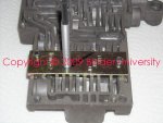
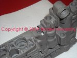
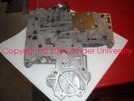
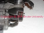
In Jesse' thread you will see an entire 727 valve body disassembled down to the last part. That is necessary in order to verify that the core valve body is surgically clean and has no issues whatsover.
If I'm installing a tf-2 kit into a functional valve body that is not contaminated, it's not necessary to tear it down that far for installing the system.
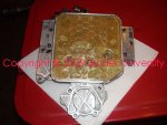
This valve body core is a "full throttle kickdown" version which is by far the most common unit used in all ihc apps through the eop of of the '76 stuff. Though it's entirely possible that someone has modded an earlier valve body using a "partial throttle kickdown" module. Some '77 and later sii use the partial throttle kickdown system, I have no preference for one over the other.
In the last several months, transgo has completely revamped this kit as compared to what they have supplied since 1975 or so. This kit is not designed for "ease of installation" and I'd highly recommend that it be installed only by a slushbox tranny pro that is experienced with the 727 box. The instructions have been majorly re-worked (but not for the better!), you must have a complete service reference also in order to tear into the valve body, the instructions will definitely leave ya hanging!!!
Some of the mods that were done with the earlier versions of this kit are no longer performed, instead...other changes have been incorporated in order to make this kit applicable to all versions of the 904/727 three speed unit (with or without a lockup converter which ihc never incorporated in any truck tranny). Ihc also never used the 904 version of a torqueflite.
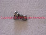
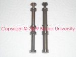
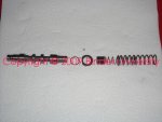
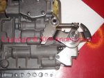
Idea here is to give you an overview of what is involved in the installation of a tf-2 kit. There a few additional parts that must be installed in the transmission itself,...in order to do that you must have the tooling needed to r&r the low/reverse servo and be very familiar with the process of doing so to prevent damaging any seal rings or rubber lip seals.
There is much more attention to detail involved in upgrading the valve body than is covered in this short how-to...the instructions do not go into that detail so I'm not going to either! This is not a step-by-step/in exact order kinda deal...each kit install will be somewhat different depending upon how far the assembly was torn down. But if anyone is interested in attempting to do one of these upgrades on their own, I'm willing to work with ya as always!
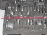
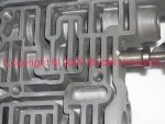
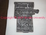
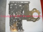
This first pic shows the separator plate marked for attention. There are many versions of this plate over the years!!! And you must make a positive id regarding which plate you are working with in order to perform the correct mods.
The steps here involve drilling out various holes using the appropriate drill bit size that is supplied in the kit.
http://www.forums.IHPartsAmerica.com/transmission-tech/2246-torqueflight-1-2-2-3-shift-points.html
One of our ihon customers, Jesse b. Has ordered up a "built" tf 727. Part of that package included a request for the installation of a transgo tf-2 shift reprogramming kit.
In Jesse' thread you will see an entire 727 valve body disassembled down to the last part. That is necessary in order to verify that the core valve body is surgically clean and has no issues whatsover.
If I'm installing a tf-2 kit into a functional valve body that is not contaminated, it's not necessary to tear it down that far for installing the system.
This valve body core is a "full throttle kickdown" version which is by far the most common unit used in all ihc apps through the eop of of the '76 stuff. Though it's entirely possible that someone has modded an earlier valve body using a "partial throttle kickdown" module. Some '77 and later sii use the partial throttle kickdown system, I have no preference for one over the other.
In the last several months, transgo has completely revamped this kit as compared to what they have supplied since 1975 or so. This kit is not designed for "ease of installation" and I'd highly recommend that it be installed only by a slushbox tranny pro that is experienced with the 727 box. The instructions have been majorly re-worked (but not for the better!), you must have a complete service reference also in order to tear into the valve body, the instructions will definitely leave ya hanging!!!
Some of the mods that were done with the earlier versions of this kit are no longer performed, instead...other changes have been incorporated in order to make this kit applicable to all versions of the 904/727 three speed unit (with or without a lockup converter which ihc never incorporated in any truck tranny). Ihc also never used the 904 version of a torqueflite.
Idea here is to give you an overview of what is involved in the installation of a tf-2 kit. There a few additional parts that must be installed in the transmission itself,...in order to do that you must have the tooling needed to r&r the low/reverse servo and be very familiar with the process of doing so to prevent damaging any seal rings or rubber lip seals.
There is much more attention to detail involved in upgrading the valve body than is covered in this short how-to...the instructions do not go into that detail so I'm not going to either! This is not a step-by-step/in exact order kinda deal...each kit install will be somewhat different depending upon how far the assembly was torn down. But if anyone is interested in attempting to do one of these upgrades on their own, I'm willing to work with ya as always!
This first pic shows the separator plate marked for attention. There are many versions of this plate over the years!!! And you must make a positive id regarding which plate you are working with in order to perform the correct mods.
The steps here involve drilling out various holes using the appropriate drill bit size that is supplied in the kit.
Attachments
Last edited: