Scout 800 Horn Circuit

Charles Brown

New member
Mayben knows the story of irmatrude, and the latest episode, wherein she attempted seppuku by spontaneously hot shorting from the battery side of the horn circuit into the portion of the wiring harness running to the front clip, while left unattended in a parking lot.

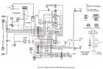
Now that I'm reconstructing the wiring harness, is there any reason not to wire the horn relay into the "downstream" side of ammeter, I.e. The charging circuit, where use of the horn will be indicated by the ammeter (just like the lights) as opposed to the factory architecture of drawing from "upstream" of the ammeter, where horn use is not reflected on the gauge? How many amps does a horn draw?

Charlie
 
Charles,
the horn draws a fairly large current 15- 20 amps in a quick spike. They May have believed the ammeter was vulnerable to needle swing damage or over current damage. Also the driver would see the big needle swing and make a call on the dealer service guy thinking there was a problem.

A ammeter like is installed in the Scout is there to give an indication of weather or not the connected load (lights, fans etc.) is above or below the present generator/alternator output current, not so much what the total system draw is. I am not sure how having the horn load indicated would help the driver. Only constant draw devices are usually connected to a system ammeter in my experience.

Because of the horns large current draw I would leave it on its own circuit on if your Scout is like the diagram attached a at least a dedicated main.

On the other hand if you are wiring the truck it to handle a higher current ammeter it would not hurt to run it to read on the meter.

Robert
 

Attachments

  • scout800_early-production_schematic.jpg
    scout800_early-production_schematic.jpg
    77 KB · Views: 9,314
Last edited:
I agree with Robert, though I'm a little conservative on the amp draw; I'm think'in around 10 or 12a. The conductor is large at 14ga. If you want it to be a switched load, as in off when everything is off, and I suppose the reason for the ammeter load side; it'll need routed through the ignition switch and that's a big load for the switch with possible system effects on the power supply(alternator or generator) as well as ignition and blinkers/flashers lights, etc. With it connected to the battery at post 3 on the regulator, the horn can get plenty of draw from the battery with little voltage drop and you can use it without having the ignition on.
 
Thanks, guys, the excellent responses!
Robert, as usual, what you explained makes perfect sense, which what I trying to get to; the factory rational for running the horn off the battery. Greg, I see what your saying, but intention as indicated was to not run the horn through the key switch, but possibly shift over to the load side of the ammeter, just like the light circuit. That means running off the charging circuit. As you mentioned, running off regulator post 3 (this is part of the battery circuit) will work, thats how its currently wired, prior to the meltdown.

Charlie
 
I'm see'in what your saying charles, but I thought too much in inferring maybe you wanted to avoid a meltdown by switching it as well. I will suggest a bigger ammeter; I've tested the stock one, and it'll peg at 30 amps and maybe not the best for night drives with your change.
 
Ok in the first place ammeters can be dangerous. I have had them cause problems before, and have seen them overheat and catch fire, burn out, or just go bad. Then your stuck. Tbh if it isnt a restoration rig replace it with a voltmeter, and fuse The power lead(not fusible link) with the appropriate fuse or circuit breaker. And even if it is a restoration install a fuse/cb inline with both the main power and and relay supply wires just as a safety feature. Replacing an ammeter with a voltmeter is simple. Just take the two leads and connect them together.
 
Back
Top