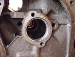
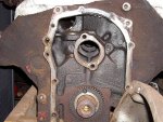
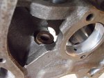
oil galley plugs

Just asking confirmation that two front plugs are installed (behind the cam gear). I am prepping to re-assemble my engine and checking off all the "little" things.

Just found the plugs in my parts "bin" so I guess the real question would be ....do I use any sealer etc on them when I re-assemble?
 

Attachments

  • DSCF0091.jpg
    DSCF0091.jpg
    136.7 KB · Views: 1,053
Last edited:
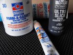
Yep, the two plugs in front, I use hylomar to seal the threads, those are 1/8"npt tapered threads. Next best thing is that oldskool permatex #2. And modern teflon-base "pipe thread sealer (pipe dope)" works just fine also.

Have ya made certain the galleries down both sides are sterilized? I use either brushes made for that purpose, or a shotgun cleaning stick with a 20gauge bore brush.

Verify that all oil holes in the cam bearings are properly aligned in the block! All the durabond cam bearings I've seen in recent years have the holes for the #1 and #2 bearings misaligned when they were manufactured, but the spit holes can be fudged by hand matching with a die grinder and then cleaning again.

Also, I don't see the oilite bronze bushing in the block above the oil pump drive boss...make sure it's knocked in also or the distributor will only last about an hour!

In this pic, I've removed the bushing for safekeeping!
 

Attachments

  • SV Gallery Plugs Front.jpg
    SV Gallery Plugs Front.jpg
    142.3 KB · Views: 1,025
Last edited:
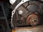
And here's a shot of the rear of the block..., only one gallery plug in that location.

Verify proper install of the core plugs in the block casting sand holes!

That trapezoidal shape plate is the thrust plate for the cam, it uses a gasket, no sealer required.

When the flywheel (or flex plate) is installed, the bolt threads must be slathered with the same sealant ya use on the pipe plugs! Otherwise, engine oil will really puke out around the bolt heads and attachment!
 

Attachments

  • SV Rear Gallery Plug.jpg
    SV Rear Gallery Plug.jpg
    107.9 KB · Views: 1,057
I installed the cam bearings. Made sure all of them lined up. Had a heck of a time with a couple!!

Ran a shotgun brush through all galleys along with brake cleaner. I will do this again right before final assembly.

Is this the bushing you mean? Or is it above this one and I am missing it?
 

Attachments

  • DSCF0092.jpg
    DSCF0092.jpg
    91.2 KB · Views: 868
Good attention to cleanup detail! That is the life of any engine build!

Yes, your pic shows the correct distributor bushing! Very important!
 
Here is some of what I am using to assemble with. I also have some permatex thread sealant(px#59214). I thought that would work on the flywheel or at least the rocker arms.(?)
 

Attachments

  • DSCF0093.jpg
    DSCF0093.jpg
    94.3 KB · Views: 722
So far today I have just checked my ring gap. And lining everthing out for final assembly. Not going to do that until I resolve my head issue. Still have to check/rebuild my oil pump. Might set the crank in and plastigage the mains while I'm at it.


Just noticed something from my pics and yours on the cam bearing orientation. The "slot" groove on my front bearing is not on the bottom like yours. I put it at the 1 o'clock spit hole. This is the only bearing I have like this (with only one groove) and I just now noticed it!! Should I switch it? Think I will just to be sure
 
Last edited:
Don't make comparisons of details like that steve! Each "brand" of engine components will be somewhat different! The cam bearings in those pics (which are totally trashed by the way!) are oem bearings. Since the manufacturer's id is on the back side of the shell, I don't know who the supplier is. The owner of that engine did not want them removed when I tore it down due some pending litigation regarding that one! That was more than a year ago and we're gonna start the build on the motor soon!

Until durabond answers my questions regarding the improper placement of the oil spit holes on the durabond in11 bearing set, I won't use those. Clevites are just fine and meet/exceed oem spec. And durabond has ignored repeated attempts at clarification for this. Right now, our durabond stocking warehouse is trying to "force" them (durabond in palo alto) to respond also. We need answers to this issue, since the oil holes don't line up, extra effort has to be expended on each engine to correct this problem.

Do both of the oil spit holes in your #1 cam bearing line up ok?? If so, that "groove" is not really important. It just kind "extends" the duration of lube available as the can rotates. If you are concerned about it, then just use a small carbide burr inna die grinder or dremel and make a groove and then lightly burnish the edges with a piece of fine scotchbrite.

All your assembly aids look just fine to me! Oldskool all the way!
 
Holes line up good. Just remembered it was the last bearing I pressed in and had to pull it off the stand and put it on my tailgate to do so.
The rear bearing doesn't have a groove either but the cam has the groove in the journal there so I didn't consider that.
These are durabond bearings:icon_eek: I had read about the situation with them in the other forums but these were included in my master kit. I figured they had to be better than what I had in it.

My concern is that even though the holes line up, they are smaller in dia. Than the originals and that this will affect oil flow to the rocker assembly.

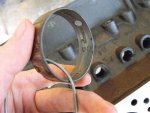
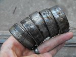
These are what I pulled out. Factory bearings!(#2)
 

Attachments

  • DSCF0094.jpg
    DSCF0094.jpg
    75.2 KB · Views: 688
Last edited:
That "reduced" diameter spit hole with the durabonds is "another" issue regarding the same set. I'm impressed you are catching all this detail! Good work!

In fact, one of our members here, "pineneedle", and I first became acquainted over this matter...and he knocked in two sets of bearings. John ended up manually "working" the spit holes back to the oem dimension using a die grinder/dremel. I know I've got pics of john's cam bearing install somewhere on the hd but can't find 'em! Maybe he'll see this thread and describe his workaround.

Buddydave tells me it was standard practice back in the factory branch when they rebuilt these engines (normally in batches of 10 units at one time), that they didn't spend too much time in cam bearing alignment. Got 'em "close" and then ran the proper diameter "aircraft" drill (12" shank with very short helix) through the ports to line up the spit holes after the bearings were in place. Then used a "de-burring" tool (hand held kinda like a paring knife onna swivel handle) to cut a small chamfer on the babbit surface of the drill bit left a rough edge. That way, spit hole alignment was not an issue as each bearing was actually matched to the block.

You are correct about making dam shore the cam bearings in your motor are right! The entire life of these engines is dependent upon that and a clean water jacket! So if it takes hand work to make the match up, spend the time to do it. Then we'll continue to ream on durabond until they respond!

Take a buncha pics of your cam bearing deal, nice detail and well focused. We need documentation of an actual durabond install regarding this issue so we can get this matter resolved. Right now though, the durabond bearings are on my "ignore" list.

 
Wish I would have enlarged them before I installed them! (more room to work on 'em.) May hafta try the dremel/drill method. Thinking now I might be better off with a new set.

Gotta say one thing though....IH rebuilds ain't no weekend thing!! Least not if ya want it done right!
 
The success of a decent engine build is in the detail! And the detail is what takes the most time! And the cleanliness of the oil passages/galleries, the water jackets (both block and heads), douching the rocker shafts, and most importantly the cam bearing setup itself are the most important points.

For matching the spit holes in the cam bearings-to-the-block, a 3/16" round carbide burr inna dremel or a miniature pnuematic hand piece works great. Fairly easy to just kinda "touch" the burr to the existing hole, but first put pieces of duct tape on the babbitt layer to protect it in case ya let the burr get away from ya. Using highest speed helps to prevent "skip" (and firm hands)!

Ya remember that trip to the dentist once where tha dude let the handpiece skip in yore mouth and ended up havin' put a filling in yore tongue??? Ya just didn't feel it at the time! Then he sed sumthin' about dentists just "practice", they don't ever really fix shit!
 
Yep, original bearings. Even have the IH logo and date code from '69 on 'em.
I believe you're right about cam thrust, eric. The thrust flange is behind the cam gear.
 

Attachments

  • DSCF0096.jpg
    DSCF0096.jpg
    66.8 KB · Views: 493
Last edited:
Yup, I just couldn't see the signs of the finger joint in the fist pic in the ones I have seen it is usually noticeable on the edge. And yes erik is right the cam thrust is at the front plate, that is what the 2nd hole in the front cam bearing is for.

The rear plate creates the transfer area to supply the lifters. That is the reason for the groove in the rear cam journal to provide continuous flow/pressure for the lifters.
 
Something near and dear to me, oil flow in an engine that one up from a wick system:smilewinkgrin:

my engine had grooved bearing for the front too, and the hole was matched to the block. Maybe you guys are right they under size it, so they can be drilled out to match the block.. I have poured babbitt bearing for large machine. Yep you got to make your replacement bearings for those machine built in the 40's and 50's. Plus drill a new hole for grease to get in there.

I have a set of bearing at the house "never" open. I could check to see if it has grooved slots for the front and rear bearing.
The front one has two holes to. Look at the pic you can see the small hole under the bearing to feed the cam shaft timing gear.


attachment.php


Here is the rear setup.

attachment.php


attachment.php
 
Last edited:
So the oil enters the cam bearing through the block, then out the hole in the back, then it turns 90 degrees in two opposite directions, then another 90 and into the lifter galleys. I think
I got it now!

Thanks for the great pics!

Julian
 
Review this thread stickyed in this forum at the top:

http://www.forums.IHPartsAmerica.co...I-4-sv-engine-non-oiling-rocker-assembly.html

Then pay attention to post #2, and download that .pdf scan of the lubrication schematic for the i4-sv engines. It's the same page printed in all IH service references, that layout never changed over the years. Types/design of oil filtration systems did change but that does not really impact what we're discussing, the plumbing loop inside the block is common for all variations.

Then memorize it and you'll know exactly how this stuff works!
 
Thanks Mike,

I have the scan and the Scout manual. I was just clarifying the previous post.

I honestly think that they put the back cam cover on with silicon. The motor has run fine for 700 miles after they figured out my oil pressure was low because the pickup tube had a cracked o-ring. This was after I paid them $1700 to pull the motor and put new rod, cam, and main bearings in it. They also rebuild the oil pump that showed no signs of wear. Only to find that the $0.25 o-ring was the issue.

I am thinking that the silicone on the back cam cover came loose and it was pushed into the lifter galleys. No this is what is impeeding the flow of oil to my lifters. And not all the lifters, just a few of them.

Please reference this post at binderplanet.
noisy liftes omg not another one!
 
Back
Top