Distributor wires

hillbry

Member
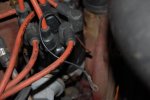
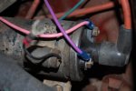
Have a 71 Scout II 345 and am finishing rewiring the rig with a 21 circuit ez wiring kit and have a question regarding the distributor and coil wires. The po had botched the wiring so bad there were splices off splices and wires not attached and on and on. I have the coil all rigged up with the new kit and am not sure what to do with the wires shown in the pics. The one in the distributor pic comes from inside the housing and the one in the coil pic is mounted on the bracket.

Keep in mind I do have a pertronix kit I am going to install once I get the rig started (hasnt been started in 6 years). I just want to make sure it starts and I do not have to sacrifice a pertronix kit if something goes wrong.
 

Attachments

  • Distributor.jpg
    Distributor.jpg
    38.2 KB · Views: 362
  • Coil.jpg
    Coil.jpg
    44.1 KB · Views: 644
Last edited:
The black wire from the distributor breaker point insulated terminal must go to the coil negative terminal.

As for the wires shown in your second picture, I have no idea what they represent. You will have to explain.
 
The wire in question in the second pic is the blurry one which is mounted to the coil bracket. I have no idea what it is and I asked a friend and he did not either any input helps thanks.
 
The small, metallic cylinder mounted on the coil bracket is a capacitor (condenser) used only for rfi suppression (radio interference). It has nothing to do with operation of the ignition system and can be removed/discarded.

For running a breaker point distributor, a 1.8 ohm ballast resistor must be installed in the feed from the ignition switch to the coil positive terminal. A second switched feed must also be fed to the same terminal from the starter solenoid to provide full battery voltage to the coil only when the engine is being cranked. This is the wiring setup only for breaker points.

The wiring for a pertronix conversion does not need the ballast resistor wiring though it can certainly run that way also.
 
Back
Top